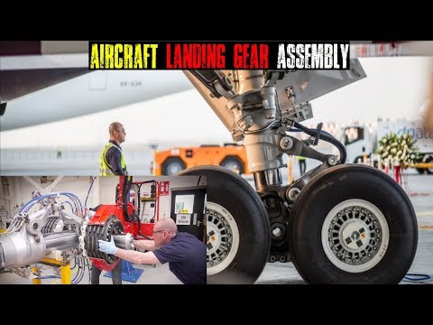
As Part 3 in our series on aerospace manufacturing, we take a close look at landing gear component manufacturing with an eye toward what tooling makers experience working with some of the largest aerospace manufacturers and subcontractors in the industry.
So far this year, we’ve gone in-depth with the manufacturing of aircraft wings and engine components in aerospace and defense. Now we’re going in-depth with landing gear components.
As one of the most critical sections of aircraft, landing gear systems bear a heavy load. Literally, all the weight of an airplane, fighter jet or helicopter is supported by the landing gear during taxi, landing and takeoff. And depending on where the aircraft is landing, as in say, an aircraft carrier in the middle of the Pacific Ocean, the materials that make up landing gear can differ.
“The retractable landing gear that is now commonplace on commercial and military aircraft was first developed for Glenn Curtiss’ Triad airplane in 1911,” writes the National Air and Space Museum in a blog post.
An airplane’s landing gear controls how it handles on the ground, but also how a plane handles in the sky, as it affects other areas including weight, performance and reliability.
We talk to three of the leading tooling manufacturers in the industry for perspective on material challenges and metal cutting nuance—and discuss real-world examples where tooling and machining made a difference for aerospace makers.
Materials Used in Today’s Landing Gear Components
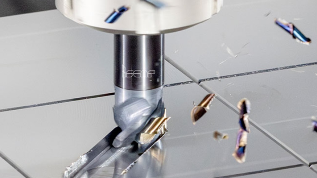
Predominantly, tooling suppliers say they see two major types of material in the large components of today’s landing gear that includes either 300M, a low alloy steel that is very hard, or Ti-5553, a titanium alloy, which is known for its strength and hardenability.
On commercial aircraft, Boeing and Airbus each use both of these materials, but it depends on the load requirements of the airplane model, says Scott Causey, an application engineer for Seco Tools.
Most of these materials types are used on any variety of these landing gear components including—the truck beam, braces, torque links and the strut, which is also sometimes called the “main cylinder.”
Source: Concordesst.com
But there are other materials used in other components of the landing gear, including aluminum, 4340 alloy steel and some titanium, which is often found in landing gear brackets, braces and links, Causey explains.
And there are other smaller components in landing gear, including flanges, pockets, reamed holes, bored holes, and many connection points, says Mark Francis, a staff engineer for aerospace and defense at Kennametal. For example, a hole could be 8 to 10 inches in diameter and 36 inches deep. You need specific tools and processes to accomplish the task.
“Another material we see for very specific aircraft carrier use cases is the use of AerMet 100—a difficult to machine, high-strength steel” says Francis. “It can withstand high-impact loads—think of the fracture resistance and toughness required for a carrier landing on the short runway of a carrier—along with being very corrosion-resistant with salt and water on the ocean.”
AerMet 100 is used almost exclusively on fighter jets bound for aircraft carriers.
Do you need a technical question answered? Ask the MSC Metalworking Tech Team in the forum.
The Most Challenging Areas of the Landing Gear Components to Machine and Manufacture
As you might imagine, the largest components of the landing gear can be slow to machine—namely because of their size. Parts like the main cylinder and truck beam, which is commonly referred to as the “axle beam,” can extend up to about 25 feet in height.
Other difficult parts include the slider, or “inner cylinder,” says Causey.
“The ID bores on these parts can run up to 70 inches long,” says Atul Sharma, an aerospace application engineer for Seco Tools. “They are very big and long. And the tolerance can be difficult to hold when cutting. Clamping can be a challenge.”
All the tooling makers we spoke to made it very clear that these big parts are often slow to machine. There is an assumption that you can machine 300M materials at a high surface feet per minute. But the reality is these large pieces are simply too heavy and big—and they require specialized fixturing to keep the parts from vibrating and to get the most out of the cutting tool.
But compared to many nickels, Waspalloys and Rene materials, these steel and titanium materials are not incredibly difficult, explains Bill Durow, a global engineering project office manager for aerospace, at Sandvik Coromant.
“In many cases, it’s the scale of the components. They’re massive,” says Durow. “And nothing’s uniform. They often have odd shapes to them, so you can’t just throw it on a lathe necessarily. Often, aerospace makers are using a large bore mill or large gantry machines, which take a lot of time.”
The tooling makers are seeing a trend of some aerospace manufacturers moving away from gantry machine and bore milling toward B-axis machining and using turn mill applications for less setups and less fixturing—and performing 4-to-5-axis profiling around the parts.
But this newer method requires more programming—and new thinking about cutting geometries to help boost efficiencies in landing gear production. It’s not uncommon for landing gear to take months to complete from start to finish.
What’s new in aerospace? Innovation in additive manufacturing. Read “The Amazing Evolution of 3D Printing in Aerospace and Defense.”
Machining Landing Gear in the Real World
Here are three examples of real-world landing gear parts and components being made where the right tooling or new approach made an impact.
Torsion Link
Challenge: A Seco Tool customer was struggling with a torsion link—an area of the landing gear that couples the inner and outer cylinders together—while cutting 10-2-3 titanium material. Cycle times were 60 hours with six distinct setups. The customer was always very behind in delivery of the parts and was about to lose its contract with an OEM.
Solution: Seco Tools worked with the customer and partners to address the customer’s machining through a partnership with DMG Mori. Seco Tools helped find a brand-new approach starting from scratch with drawings, models and tooling.
Outcome: The customer reduced part-making and tooling setups from six to two—and decreased cycle times from 60 hours to 23 hours, or 62 percent. It boosted production and allowed part delivery to be on time. Ultimately, the solution allowed the aerospace manufacturer to keep its contract.
Tooling Designed for the Material
Challenge: A 400-pound forged landing-gear component made out of Ti-5553 was burning through tools for a Kennametal customer. The customer was programming a brand-new tool change every 30 minutes. When finished, this part is about 210 pounds. But this titanium material had an alpha case that was difficult to break through.
Solution: Kennametal used milling cutters with a helix design with 8-sided inserts and drills designed specifically for this specific and tough titanium grade.
Outcome: Roughing time went from 25 hours to 15 hours. Cycle time was reduced by 40 percent. Tool life was boosted by 300 percent: Tools now lasted 120 minutes before a new cutting edge was needed.
A Fresh Approach Using an Existing Tool
Challenge: Parts for landing gear components were getting a lot of 5-axis and tool movement as an incumbent tool was picking up the back of the insert—and breaking off the screw as the cutter had an eye lock to keep it tight. The aerospace customer had to stop its production too often, as parts required too much manual intervention and babysitting. Things were moving too slowly.
Solution: Sandvik Coromant applied a tool originally designed for blade machining in horizontal machining and applied it to this vertical application—and suggested ramping or “healing” the tool so that it was raised a tiny bit, two to three degrees, to avoid back cutting the tool. It also used techniques for round bossing and it performed very well.
Outcome: Process security. The insert movement went away. Insert screws weren’t breaking anymore. And the customer was able to stop babysitting the process and move to a more “lights out” production environment. The operators could work on multiple machines simultaneously.
How are you dealing with shrinking cycle time in your aerospace manufacturing? Talk to your peers in the metalworking forum. [registration required]