Introduction
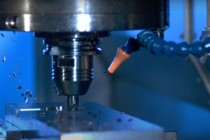
Manufacturers employ turning, milling and drilling operations to machine features on workpieces. However, those same processes can also produce burrs and undesirable sharp edges at the feature borders. These edge conditions may result in material breakage when the part is in use, can structurally weaken it and may pose a danger for those handling it. These negative conditions are why many end users consider burrs or extremely sharp edges as reasons to reject parts from suppliers.
Manufacturers have traditionally removed burrs and sharp edges using hand grinders and other manual processes. Such methods are slow and require that the part be taken out of the machine tool and refixured for the deburring or chamfering operations. And even when performed by skilled craftsmen, these operations lack the necessary process consistency when going from part to part.
A productive alternative to manual deburring is Mechanized Edge Profiling (MEP). MEP eliminates unacceptable edge conditions by applying an engineered tool and the same equipment that machined the part features. The MEP process offers numerous benefits. It enables the final edge condition to be exactly defined and programmed through the machine’s CAM system, resulting in maximum repeatability. Overall part production time is reduced because the part does not have to be removed from the machine and refixtured, and tolerance stacking and other inconsistencies that occur from setup to setup are eliminated. In response to this trend, today’s cutting tool makers continue to develop new and productive tools that enhance the benefits of the MEP process.
Prime Candidates for MEP
Considering the aerospace industry’s increasingly rigorous demands for part accuracy and consistency, jet aircraft components are prime candidates for the application of MEP.
Aircraft turbine engine components, for example, are generally categorized as non-rotating and rotating. For MEP of non-rotating engine parts such as drums and casings, edge profiling usually consists of standard chamfer and break edge tooling, applied on the equipment that machined the part.
For critical rotating parts such as fan and compressor discs, end users have higher standards and demand complete elimination of surface imperfections. Edge conditions typically must undergo lab approval and certification. To deburr these parts, toolmakers have developed high-accuracy, fully repeatable, custom MEP tooling.
MEP Tool Development
Standard deburring and profiling tools, such as those applied on non-rotating components, include coated solid-carbide chamfering end mills with 45˚ and 60˚ cutting edges, as well as tools that use indexable inserts to produce 45˚ and 60˚ chamfers.
For the most critical applications, toolmakers provide tools custom-engineered to profile edges and remove burrs specifically at the entry or exit of a hole. Some tools combine those capabilities and can remove both entry and exit side burrs.
These custom tools often feature complex cutting geometries. The most sophisticated have edge designs that produce a chamfer with a radiused edge that is preceded by lead-in and lead-out angles engineered to prevent formation of secondary burrs.
Specialized tool development goes beyond the cutting edges alone. For profiling burrs and edges at a hole entry, or top surface of a component, research has revealed that the combination of a right-hand cut with a right-hand helix is most effective because it serves to remove the cut material from the part. On the other hand, for exit burrs on the bottom surface of a part, a right-hand cut combined with a left-hand helix works best, again because that configuration moves chips away from the component.
Other application analyses have indicated that MEP tools engineered for removing burrs at the top or entry of a hole provide longer tool life than tools intended for removing burrs at the bottom or exit end of a through-hole. That is because a deburring tool designed to reach through a part to access the hole exit will be longer and smaller in diameter than one intended to do its work from just one side of the hole. A longer and smaller-diameter tool is more prone to instability and vibration, both of which can chip or break a carbide tool. As a result, most shops opt to use separate tools to deburr the entry and exit edges of a hole rather than a single tool that can do both.
Longer, smaller-diameter tools also require more care with regard to choosing cutting parameters. A short, sturdy tool can run faster without vibration or other problems. Part geometry and features make a difference as well. When cutting conditions are stable and cuts are smooth and uninterrupted, more aggressive cutting parameters can be applied. On the other hand, part features such as access holes that interrupt MEP cutting paths force the use of more conservative parameters as to minimize tool wear and prevent premature failure.
Part of the ongoing development of MEP tooling involves tools that combine machining of a feature with deburring. For instance, the MEP cutting edge would be located at the top of the end mill so it could simultaneously machine the diameter of the hole and deburr the entry edges.
Material Challenges
Many aerospace materials, in regard to their machining characteristics, present additional challenges when it comes to removing burrs and chamfering their sharp edges. Nickel-base alloys used in engine components, for example, are tough and are poor conductors of heat. Thus, the cutting tool absorbs the heat generated in the cutting process, which accelerates tool wear.
Accordingly, when determining the metallurgy and geometry of a tool, toolmakers have to strike a balance between edge sharpness and edge strength. A hard carbide substrate material may resist thermal and abrasive wear very well, but it will lack the impact resistance of a substrate that features additions of cobalt or other alloying material to increase its toughness. In the same way, a dead-sharp cutting edge may be more prone to breakage as compared with one that has a hone or other edge-rounding preparation. Toolmakers also fine-tune rake and helix angles as well as tool coatings to achieve the best results with specific workpiece materials.
Tool Size
For processing large holes and edges, toolmakers can design tools of any size for which suppliers can provide a large enough blank. On the small side of the spectrum, however, there are limits. Currently the smallest radius that can be ground is about 0.2 mm, with proportionately smaller lead-in and lead-out angles.
Custom MEP tools have specific radii, chamfers, angles and combinations of those features. The tools commonly have square cutting edges. However, ballnose and lollipop-style tools are also available to profile features of a component whose contours restrict access of a square-edged MEP tool. Applied on a five-axis machine, these tools can scan the line of a complex part profile and create a radius on long contoured edges.
MEP in Operation
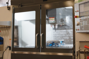
To maximize accuracy and consistency and save the time spent moving a part from machine to machine, manufacturers usually perform MEP as a portion of the actual part feature machining operation.
Typically, deburring occurs after all machining operations are completed. The CAM program directs the MEP tools to deburr all the holes and break sharp edges in sequence. Some MEP tools can be used to deburr a variety of holes, and some profiling tools can be applied on three or four different locations or features, such as the bottom of a hole as well as the bottom of a scallop contour.
To ensure that the edge profiling takes place in the correct location and with the proper amount, the hole or feature involved must be defined or measured before the MEP operation begins. When part tolerances are very tight, the location of the part surface is well defined and in-process measurement may be unnecessary. However, when tolerances are generous, measurement is necessary after initial machining to determine the location of the edge or feature to be profiled.
In addition, the tool itself must be measured and located to ensure that it will profile the part correctly. Because the tool radii are so small – and for practical purposes, unmeasurable – the tool length is specified in the CAM program. The operator can confirm the tool length away from the machine with a presetter or on the machine via a laser or touch probe. Feed rates are calculated relative to the measured dimensions of the part features and the tool. The most sophisticated custom deburring tools are 100 percent measured by their manufacturer to a tolerance of 40 microns on the tool profile, including runout.
The deburring or chamfering operation should be considered as a finishing pass, with the primary focus on quality. Productivity is always important, but especially in the case of aerospace components costing hundreds of thousands of dollars, pushing the tool to maximize output can have negative, and expensive, repercussions. Consistency, reliability and elimination of scrap parts are paramount.
Conclusion
Parts with out-of-specification sharp edges and burrs are more and more frequently considered to be expensive scrap. This is strongly evident in the aerospace industry, but is a growing trend in some critical applications within the medical, energy and other industries. Manufacturers need a method to deburr components and profile part edges that is consistent, documentable and cost efficient. Mechanized Edge Profiling (MEP) fills that need because it replaces manual operations that, no matter how skillfully performed, can be inconsistent from part to part and are expensive in terms of labor, setup and part handling expense. Some end users have already banned manual deburring because it cannot be documented and certified.
The most efficient and cost-effective MEP represents a combination of engineering development and application expertise. Toolmakers that offer such a total solution will help streamline the aerospace manufacturing process (as well as similar processes in other critical industries) and produce new levels of quality and productivity.
MEP in Action
Mechanized Edge Profiling is benefiting manufacturers in a variety of applications.
In one situation, a manufacturer was producing a 303 stainless component in a twin-spindle machine. As part volume and batch sizes grew, so did a need for increased productivity. The operations were unbalanced and time-consuming – 90 percent of the machining took place in the main spindle, and manual deburring of the underside of the part was required, necessitating an additional setup. When the manufacturer applied a custom-designed solid-carbide MEP tool in the machine’s subspindle, it enabled profiling of both sides of the part’s flange bolt holes at the same time. Machining time between the two spindles became more balanced, and cycle time decreased significantly. Use of the MEP tool also eliminated the need for manual deburring and the extra setup and time it required.
Another case involved a choice between a chamfered (flat) edge treatment versus a radiused (rounded) edge. Some parts do not have specific requirements that an edge be processed by either style of tooling. One manufacturer, however, found that when applying a radius instead of the chamfer, part life was three times longer than a part that was chamfered. A seemingly small difference in tooling choice increased part quality significantly.
Finally, an aerospace manufacturing operation on a TiAl-4V fan disc provides an example of the application of an MEP contouring tool. A manufacturer had been using a carbide form tool held in a cam fit holder to machine the disc. Surface finish was poor at random locations around the disc and slot radius, and the problem was inconsistent and varied in severity and frequency. The manufacturer applied a 10-mm diameter, 10-tooth center-cutting lollipop-style coated solid-carbide cutter with 30˚ right-hand helix. The tool eliminated the surface finish problems, and it was able to finish both sides of the disc in a considerably shorter amount of time.
Talk to Us!
Leave a reply
Your email address will not be published. Required fields are marked *