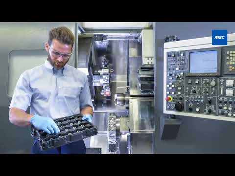
One of the greatest improvement opportunities available to any machine shop is offline presetting, which requires quick-change tool holding.
If you’re still using Weldon shank end mill holders, there are far better options available today, such as mechanical milling chucks and hydraulic tool holding grip tools, that are far more accurate.
Several tool holding manufacturers have developed proprietary systems to prevent helix angle moving and sliding.
Polygon-style tapers become increasingly prevalent in live tooling and multitasking machines with true milling spindles.
If you are stuck wondering why your machine’s not as productive as you need it to be, it may be time to evaluate your tool holders. Tools alone are not the answer.
Without the right tool holder, you’re going to fight an uphill battle all day, every day. Tool life will be poor, productivity’s going to suffer and worst of all, you’ll be unable to make quality parts. Whether you operate a basic 3-axis machining center or a 9-axis multitasker with greater machining capabilities than every other CNC machine in the shop combined, proper tool holding technology is essential.
Tool holders have evolved—and so has the opportunity to evolve your machining production by better understanding the value of setting up tools for maximum balance, spin and accuracy.
The Importance of Staying Stationary and Offline Presetting
But what does “right” mean?
How does a tool holder improve throughput or part quality? The answer depends on the tool and what that tool is intended to do since the tool itself will determine the relevant cutting forces. Does it have a round or square shank? Is it for milling, drilling, turning or boring—or something else?
Let’s start with a simple example: an indexable turning tool in a lathe application. For most shops, this is easy—just clamp the tool in and get to work.
But what about setup time?
Swapping out a 1-inch shank square holder means loosening a couple of bolts, cleaning the various surfaces, clamping the new tool in place and touching it off. If you’re fast, you’ve probably burned up five minutes. And yet you’ve also just eliminated one of the greatest improvement opportunities available to any machine shop: offline presetting.
Presetting can’t be done without quick-change tool holding. Granted, the mounting blocks needed to convert a lathe turret to quick-change modular tooling aren’t inexpensive, but a quick ROI evaluation should convince shop owners that it’s well worth the investment.
Rotary Tool Holding and Shrink-Fit Tool Holders
Another area that might be in need of an upgrade is your rotary tool holding situation. On a lathe, repeatability and centerline are all important, but machining centers require those attributes and more. Consider tool runout: If you’re still using Weldon shank end mill holders, there are far better options available today. Mechanical milling chucks and hydraulic tool holding grip tools are far more accurate than their century-old predecessor with none of the radial displacement that comes with a Weldon side-screw.
Mechanical milling chucks and hydraulic tool holding grip tools are also inherently more balanceable (see Sidebar). Shrink-fit tool holders, which have no moving parts and are the most balanceable of all tool holding systems, require an investment. They also need to be installed with a special shrink device—preferably an induction-style system—but are often the first choice for gripping carbide shank drills and end mills (not steel). When properly applied, they offer best-in-class runout and gripping strength.
If you’re still using Weldon shank end mill holders, there are far better options available today.
Stop Scrapping Tools with Proprietary Tool Holders
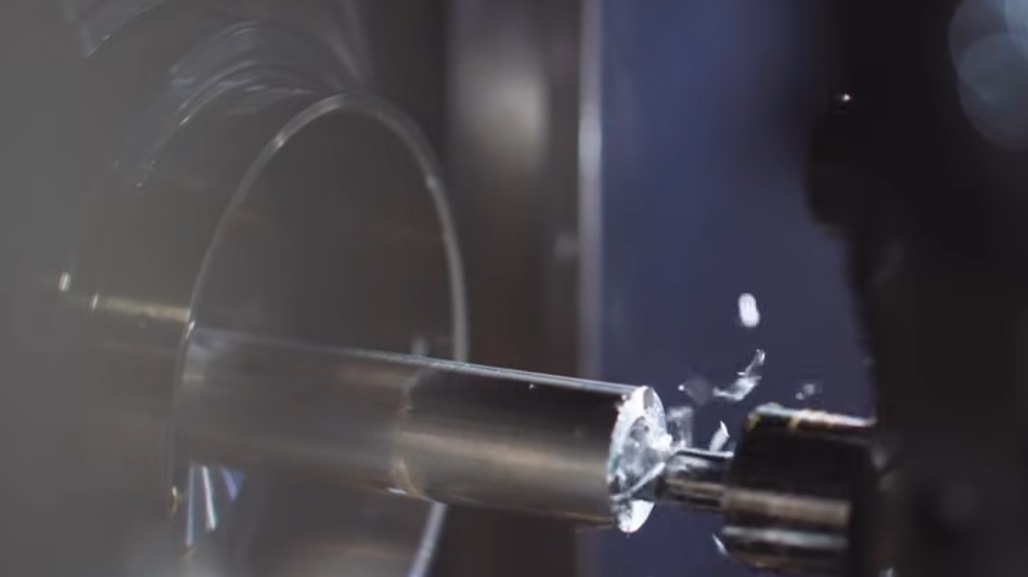
High radial cutting forces during milling can cause even the most tightly clamped end mill to move within the holder. In most cases, the helix angle then causes the tool to slide outward into the workpiece, possibly scrapping it. Yet several tool holding manufacturers have developed proprietary systems to prevent this moving and sliding. These systems rely on threaded connections, wedge locks or comparable mechanical means to prevent tool movement. Some employ these anti-pull mechanisms within mechanical milling chucks, others within shrink-fit holders, and some even leverage the Weldon flat.
Modular-style tool holding, which offers screw-on carbide drill bits, end mills, chamfering tools and other “inserts” that can be replaced in seconds, eliminates the need for collets or chucks and provides a rigid, accurate connection with no touching off or presetting required. They might cost a bit more but are well worth the price given their greater productivity.
What’s your take? Talk to your peers in the community forum .
Finally, take a look at the spindle connection itself. You might be stuck with whatever taper is on your current machining center, but that doesn’t mean you can’t buy the best tool holders available for it. Verify that they meet the advertised standard by qualifying the taper and flange dimensions on the shop’s coordinate measuring machine. And if you are in the market for a new machine, evaluate the merits of an HSK (which means “hollow-shank taper” or its official full name, “Hohl Schaft Kegel”) or comparable alternative to the steep-taper status quo. Whichever way you go, be sure to embrace a routine maintenance procedure for machine taper and tool holders alike. Each should be cleaned and inspected regularly for wear, and the machine drawbar force should be checked with the appropriate instrument.
Turnabout Is Fair Play in Live and Turret Tooling
Do you have live tooling? How about a multitasking machine with a true milling spindle? Polygon-style tapers become increasingly prevalent in this arena. As for the turret tooling, some favor the VDI standard, others use BMT (base-mounted turret) using a polygon or short taper tool holder interface. Each has its pros and cons, but both should be used with proper gripping technologies or with a high-quality ER or TG-style collet. Take note: Avoid side-lock holders wherever possible to minimize runout.
What kind of tool holder setup does your shop use? Tell us in the comments.