Share

Speed, while essential, does not take precedent over predictable, reliable outcomes in aerospace and defense manufacturing.

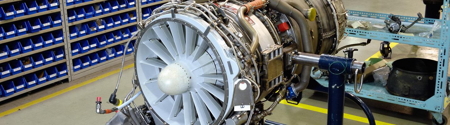
For this first article in a series about building aircraft, we focus on engine parts and components, highlighting the real-world problems tooling makers help their customers resolve every day. We also take an in-depth look at what’s going on in and around aerospace part-making right now.

What’s the state of the aerospace and defense industry right now? The push to build aircraft fast and deliver on time is very real—but it’s not without its obstacles or costs.

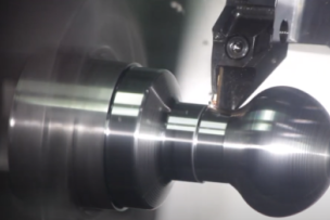
At the part-making level, heat-resistant and composite materials can be downright tough to cut. Consequently, aerospace manufacturers are having to become very strategic in their process engineering, machine programming and tool selection, according to three major tooling makers we interviewed.

Becoming strategic is very true for all of the complex components that make up a jet engine where individual $75,000 forged parts are the norm—and scrapping one is an expensive, undesired option. Speed, while essential, does not take precedent over predictable, reliable outcomes.

Aerospace and Defense: Production Boost Means Advanced Tooling Strategies Are Needed

“As we see original equipment manufacturers increase production rates, there remains a risk of suppliers facing difficulties in ramping up production,” says Robin Lineberger, the leader of Deloitte’s aerospace division, in the “2019 Global Aerospace and Defense Industry Outlook” report. “To overcome this challenge, manufacturers should consider deepening their focus on strengthening the supply chain, effective program management, and the use of advanced technologies to enhance productivity and efficiency.”

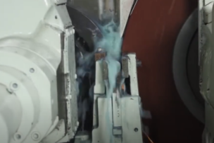
In its report, Deloitte expects 2018 to close with some 1,600 aircraft for the year—and predicts 100 more than that coming for 2019. The production demand often means using higher throughput and multitasking machines. The “advanced technologies” it mentions include everything from in-process sensor-based metrology to high-speed, multiaxis machining to highly engineered, specialty tooling intended for whatever material specifications this highly regulated industry throws its way.

What Deloitte doesn’t point out is that an advanced 5-axis machine can take six months to a year to arrive. So while those are on back order, some subcontractors are managing with existing 3-axis systems or other aging machinery—and many finished aerospace parts “suppliers” are having to rethink tooling strategies while they wait, explain tool makers.

“They want quicker ways of manufacturing,” says Bill Durow, a global engineering manager with a focus on aerospace at Sandvik Coromant. “They want to run them at higher speeds whether roughing or finishing. Today, the volume of engines that are being produced are at a rate we’ve never seen before in the industry.”

Finding the right grades and insert tools designed specifically for heat-resistant superalloys, aka “HRSAs,” is very possible today. But there is still a learning curve about these newer materials and the geometries needed to cut them, say the tooling makers.

Tools designed to cut 4140 steel, for example, are likely not the best tools to cut Inconel, titanium or carbon-fiber reinforced plastic, or “CFRP.” In the past few years, some static and rotating engine components that used to be made of titanium are now being made of ceramic matrix composite materials, or “CMCs,” say engineers from Seco Tools.

“The art of all of this is the synergy of putting it all together,” says Dave Todd, western zone and aerospace manager, at Seco Tools. “Our skills today have changed in aerospace, and we have become much more of a consultancy working with technology partners, first-tier suppliers and academia … A lot of the process engineering is done off-site at our technology hub.”

All three tooling makers have test labs that they use to proof-out potential solutions for their customers. All three also prefer to do a mix of lab-based testing, as well as on-site testing to make sure the exact strategies work on the actual, physical production line.

Thinking about part-making opportunities in aerospace and defense? Read “Manufacturing 101: Becoming Part of the Aerospace Industry.”

The Problem and Solutions for Managing Heat in the Cutting Zone

Fuel efficiency is driving the demand for lighter weight components using heat-resistant materials that can be hard to machine. Part of the impetus for more efficient engine performance is environmental: A cleaner burn is also more efficient.

“The engineering requirements draw it down to the supplier level—meaning you have to have a faster response time on tooling technology to support advanced materials,” says Scott Causey, a market segment specialist at Seco Tools. “And some of the materials may require a completely different tooling strategy to cut simply based on their complexity: A regular HRSA material does not use the same cutting strategy as a ceramic matrix composite.”

A CMC material is layered and can break easily if not handled correctly.

But also think about this: Heat-resistant material—which is excellent for the efficiency of an insanely hot turbine jet engine—also creates a lot of heat when cutting. The tool grades require a level of heat resistance themselves to even get the job done.

To help meet the need for coolant, through-the-tool delivery has become an essential detail in tools for advanced machining. Tool makers are consistently finding new innovations in coolant delivery—including some tools that have multiple ports to deliver in the most immediate cutting locations at the most effective time.

Speaking of coolant: Where’s cooling technology headed? Find out in “The Future of Metalworking Fluids, Machine Lubricants and Coolants.”

Spotlight on Aircraft Engines

The geometries needed to cut engine-part shapes and materials require dimensional thinking. There are uniquely shaped engine blisks and air foils that may combine different materials—a composite with titanium, for example.

To combat that, these makers design and test a full array of grades intended to cut the most challenging materials—Inconel, HRSAs, titanium and many others. And there’s one other way: They build custom aerospace tools as needed. These custom tools often become standard product lines for all customers.

Three of the major tooling makers describe how the OEM specifications and unique geometries of aerospace parts have driven custom tooling toward becoming standard product lines—once proven in the field. All three makers have programs for aerospace—and very specific parts optimized for today’s engine component applications, including: blisk/impellors, airfoils, turbine discs, turbine casings, spools, fan casings, and shafts.

Side view of internal aircraft engine components. Credit: Sandvik Coromant.

Here are four examples of real-world engine components being made where the right tooling made an impact. All include Tier 1 aerospace manufacturers with an average of 35 to 40 machines in their shop that run 365/24/7. These are by no means the only areas of the engine component offerings for these makers.

Sandvik Coromant Tackles Productivity in Blisks

Challenge: It was taking seven days to make a blisk. The nickel-based part had a deep blade and a narrow slot. Roughing the long-reach proved ineffective with traditional milling approaches. Chip packing was excessive. Machines were crashing.

“We saw what they were doing, just burning up end mills, at full slot: Back and forth, back and forth, back and forth,” says Durow. “They had redundant tools, they’d take them to the regrind shop, then reuse them … It was taking a lot of time and using a lot of end mills.”

Solution: A solid-carbide plunging tool similar to what had been done in die and mold operations. In addition, a second tool with a smaller diameter was then used to clean up the cusps.

“We brought our test piece back to the lab, and we came up with the idea to use the plunging routines,” says Durow. “It worked really, really well. And the nice thing was that we nearly eliminated another semi-finishing operation with the secondary cleanup.”

Outcome: Shaved four days off the seven-day blisk production with roughing and semi-finishing. It also ended up becoming a standard offering for blisk applications.

Kennametal Saves a Big Purchase with an Air Foil

Challenge: An irregularly shaped air foil made from Inconel was being cut in an electrochemical machining process, or “ECM,” where the workpiece was being held by a Bismuth alloy material. Aggressive cuts of the raw material were not possible, so production was slow. Pulsating forces were causing chatter and vibration—and poor tool life.

Solution: Designed a cutting strategy that adjusted the helix, the flute count and the microgeometry of the tool to minimize the push off into heavier cuts. For lighter cuts, they increased the helix and changed the diameter and flute count to make sure there were three points of contact through the rotation.

Outcome: Smooth cutting, increased tool life and increased maximum metal removal rates. The customer was able to cancel the order for a $1 million new machine that was about to be ordered.

Seco Tools Takes Control of Cut Grooves in an Engine Disk

Challenge: Chip-control problems from cutting deep grooves in heat-treated Inconel 718 in a compressor disk that holds the fan blades. Deep plunging routines lead to tool breakage and poor tool life.

Solution: A multidirectional turning and grooving system combined with high-pressure coolant. A zigzag, ramping geometric cutting strategy helped thin chips, reduce heat and gain considerable tool life.

Outcome: A 15 to 20 percent reduction in cycle time. Gained control of the process and lessened the burden for manual, time-consuming intervention.

Kennametal Eliminates Vibration in an Engine Casing

Challenge: Removing a full inch of titanium for an engine casing but it could not be turned. There was too much cutting force and little productivity from existing tools. It was hard to get around specific feature areas.

“Engine cases are supposed to be round, right? But they’re really not,” says Mark Francis, project staff engineer for aerospace and defense at Kennametal. “They’re chock-full of features that eliminate the ability to just do a simple turning cycle … I would say 80 percent of the time, material is cut by milling.”

Solution: Use a specialized tool that could fit around the diameter and simultaneously eliminate vibration and push off.

Outcome: A stable, reliable production line with predictable metal-cutting efficiency. Custom tools that lead to becoming a standard.

The Importance of Production Process and Cost Per Component

Keep in mind: Most Tier 1 aerospace part-making suppliers are not running the same exact machining equipment—even though they may be building the same parts from the same OEM specifications. Tooling makers and metalworking specialists have to understand each machining environment and design strategies that work for every unique machining environment.

Independently, all three tooling makers, who are competitors, wanted one thing to be abundantly clear: The emphasis should be on the productivity gains from using the right tools intended to really make an impact on productivity and accuracy. They also believe a more holistic view of the cost per component metric helps meet on-time delivery of more and more aircraft.

The proof, they say, is in the productivity.

Are aerospace production rates for real? Jump in on the conversation over at the metalworking forum. [registration required]

Talk to Us!

Leave a reply

Your email address will not be published. Required fields are marked *

MSC

Signing into Better MRO is easy. Use your MSCdirect.com username / password, or register to create an account. We’ll bring you back here as soon as you’re done.

Redirecting you in 5 seconds