Adding rotating tools to turning centers means you can combine several set-ups in a single machine for a more streamlined and productive machining process. To accomplish this, turn-mill machines were introduced in the 1990s. The initial idea was to enable driving a milling cutter, drill or threading tap on one or more tool positions in the turret to eliminate limitations of polar interpolation and other related programming difficulties.
To improve reach, an extra set of ways was added to move the rotating tool across the spindle face. This was accomplished by mounting the tools on revolver sides or on its face, by installing the Y-axis ways on a slanted bed or by using an independent milling head. Both machine tool makers and manufacturers soon recognized the benefits of integrating both milling and turning operations.
Today, the Y-axis option has become a standard feature in most multi-task machines and optional in many new turning centers.
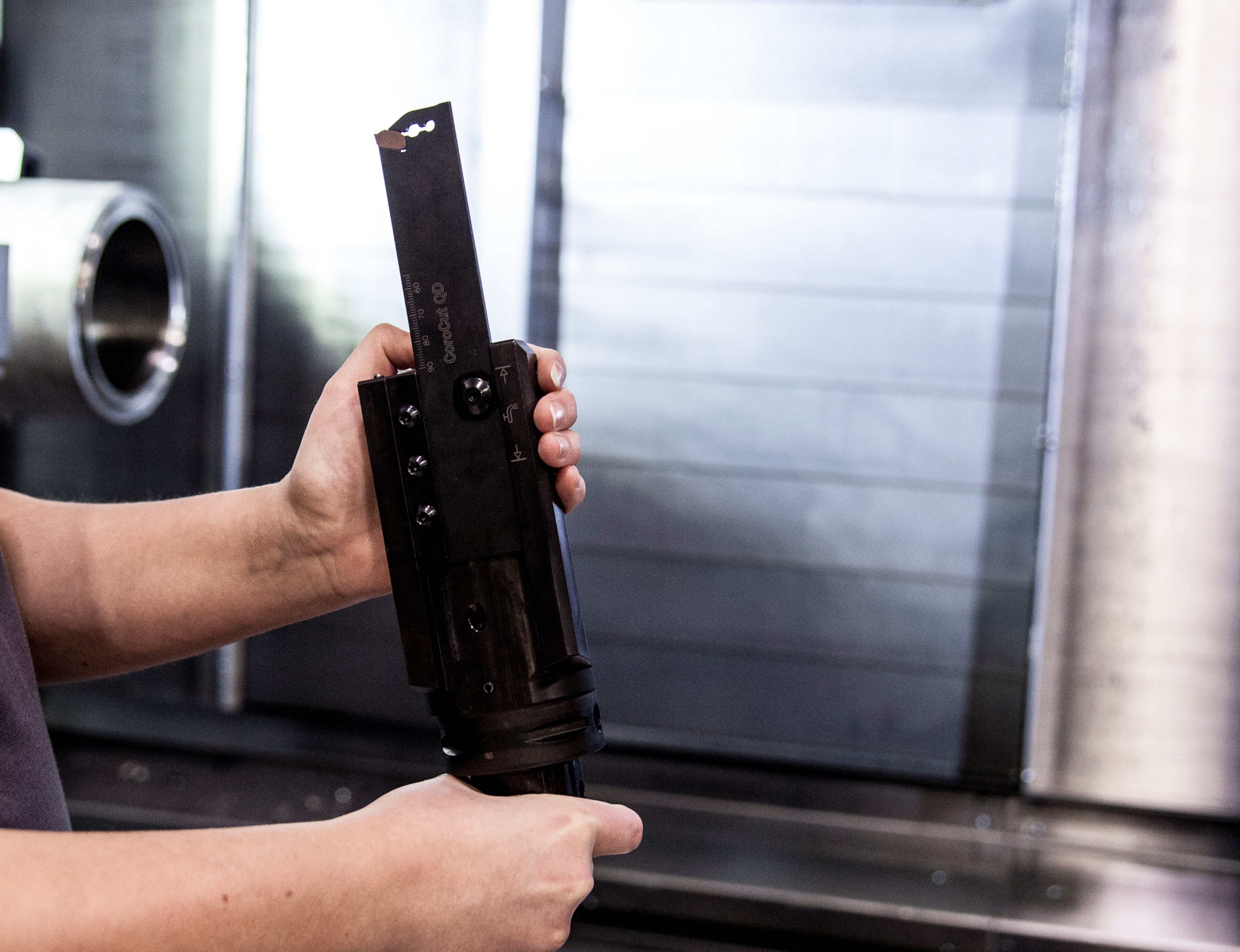
As a potential tool breakage risks leading to costly machine downtime or scrapped components, parting off is a stage of the machining process where manufacturers don't compromise on security. To meet the high demands put on these type of tools, the system CoroCut® QD was developed by Sandvik Coromant in 2013. While considering how to improve this high-performing system even further, the tool developers started looking at these modern machines with Y-axis capacity. This resulted in an innovation that involved more than just the tool design but also a completely new method: Y-axis parting.
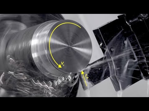
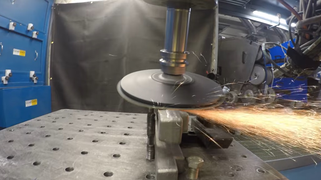
View this short video for a demonstration of Y-axis parting with CoroCut® QD.
The Y-Axis Parting Principle
The principle behind Y-axis parting is incredulously simple. While conventional parting off tools align with the X-axis of the machine tool, the Y-axis tool has simply been rotated 90° anti-clockwise to align with the Y-axis. In a conventional tool configuration, the relatively long and slender parting blade and holder is fed at a 90° angle into the rotating workpiece. The largest cutting force is generated by the cutting speed and the rest by feed motion.
The consequence is a resultant force vector that is directed diagonally into the tool at an angle of roughly 30°, in other words across a very weak section of the blade. To avoid tool breakage, this is compensated by reducing the blade overhang and by increasing the blade height, which in turn sometimes compromises the usability of the tool.
By turning the tip seat 90° and utilizing the Y-axis, the tool can cut its way into the workpiece essentially with its front end, which nearly aligns the resulting cutting force vector with the longitudinal axis of the blade. FEM analyses performed by the Sandvik Coromant R&D team confirmed that the new solution eliminates critical stresses and increases the blade stiffness by more than six times compared to conventional blade design.
To put it short, when switching to parting in the Y-axis plane you get a beneficial direction of the cutting force resulting in less instability and vibration. This means you can ramp up feed rate without losing stability or breaking the tool for an extremely secure and productive parting process. Simple as that.
Download a PDF of Sandvik's handy infographic showing the Five Reasons For Y-Axis Parting here.