Bye-bye, lap lines and stress risers. Smooth is the name of the game. Learn all about the tools and techniques needed to remove metal from aircraft wings.
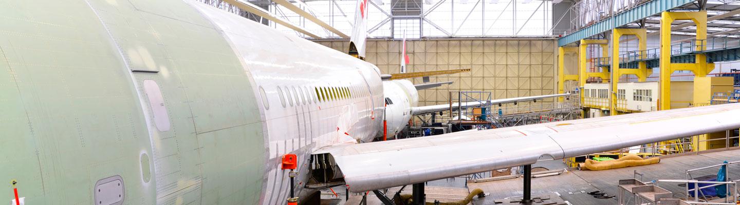
What does it take to make aircraft wings in today’s hyperproductive aerospace industry? As Part 2 in our series on aerospace and defense manufacturing, tooling makers explain how they are helping the industry find more and more hours to shave from the process.
Wings are not necessarily considered the most difficult part of a plane to manufacture—but they are large and require big, wide-open horizontal machining and several days to make. As with all aerospace and defense manufacturing, the business challenges are about finding efficiencies while maintaining the highest production quality.
Demand is high—and business is booming. The major aircraft makers are producing anywhere from 40 to 60 commercial aircraft a month, depending on the model, according to tooling makers we interviewed.
The manufacturing of wings themselves has not changed a tremendous amount over the years, unlike engine components, which have had a lot of variation. In some cases, engineers have been modifying some of the wing’s materials—sometimes using more exotic titanium.
Overall, the materials for wings stay in the titanium camp, such as Ti-6AL-4V, or in the aluminum camp, where 6061 is prevalent—with a little bit of 7075. Some wings are also made with carbon fiber reinforced polymer (CFRP) and aluminum lithium—which are found in rockets and spacecraft.
Better MRO spoke to engineers from three major tooling makers at Kennametal, Sandvik Coromant and Seco Tools about best practices in tooling for wings and the parts attached to the wings—including pylons.
Aircraft Wing Design: Aircraft Rib, Wing Spars, Stringers
An aircraft wing structure is comprised of a skeleton and an outer skin. The skeleton of the wing consists of three main components: spars, ribs and stringers. The spars extend along the span of the wing and help control the amount of flexing, while the ribs form the wing’s aerodynamic shape and run from the leading to trailing edges.
Stringers span between the ribs, parallel to the spars and are used for stiffening the wing. Together, this skeleton must not only support flight loads, it also supports the engines, houses many internal components and holds a large volume of fuel.
“Some of the harder aluminum alloys, such as 7075, require a very tough grade of carbide to cut and maintain acceptable tool life,” says Mark Francis, staff engineer, aerospace and defense, in Kennametal’s solutions engineering team.
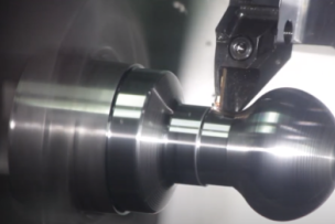
“For the wing skins, it’s a face mill-style tool. Depending on the size of the wing, you want a very large diameter tool so that you can cover more surface in a shorter amount of time. There are also many features to cut inside the wing for things to attach,” explains Francis.
The goal here is to be able to cut all the mounting features with the least number of tools to limit the time in changing tools. When removing material from the skin, it’s all about attaining an extremely smooth surface using a large gantry type of machine. This is not about using hand tools. It’s meant to be as automated and exacting as possible.
“The details of the geometry of the cutting tools can have an impact on metal removal rates (MRR),” says Eric Gardner, North American application specialist at Seco Tools. “With the right adjustable geometries, manufacturers can see upward of a 30 percent increase in the MRR, which can often translate into a 15 to 20 percent boost in part-making productivity.”
Source: Aircraft Systems
“The finish has to be really, really smooth on these spars and mounting feature areas,” says Francis. “We’re generally using a slotting-style cutter or finishing cutter here … There can be no ‘lap lines,’ which is a line that runs down the length of the cutting surface that could be caused by the mismatch of a couple of the inserts along the width of the cut.”
Lap lines are stress risers—and there is a lot of stress inside a wing, so if a stress riser or lap line exists, it’s a bad situation. The wing will be rejected and will have to be re-machined or scrapped. For a part this essential and large, scrapping one is a terrible and expensive option.
To help eliminate lap lines, aerospace manufacturers are often using adjustable wheel cutters with 10 to 12 inch diameters, with carbide inserts specially designed for aerospace grade aluminum alloys with multiple configurations for the cutter bodies, says Francis.
“And the carbide insert has to be running perfectly true to the next one, so the runout has to be zero. The only way we can really achieve that is to make the tools adjustable,” says Francis. “The customer adjusts each one of those inserts to a particular diameter, so that when the tool is running down the spar, the lap lines are eliminated. And that's a definite must ... We can't have any kind of inconsistency.”
Potential Problem Area: Chip Evacuation on the Wing Skins
When removing metal on the wing skin, the wing itself for very large aircraft can be several hundred feet long. It’s not exactly flat, but there is plenty of metal to cut away on a huge flatbed—and to make smooth.
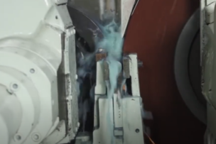
“In many cases, there’s a vacuum system used to pull the chips off the face of wing skin,” says Francis. “Those chips can get stuck as the insert is coming back around again, and re-cut and smeared into the material. And that is an absolute no-no. We don’t want that.”
To help avoid that situation, tooling makers adjust the geometry to allow the chip to be evacuated quickly and sucked up with a vacuum without getting brought back into the cut. Often on these flatbeds, manufacturers are using a light mist to help with the chip evacuation or dry cutting—since it’s such a large and open area for these large wing skins.
There’s so much to understand about making aircraft. Go deeper. Read “Built for Speed: Making Quality Aircraft Engines On Time.”
Defense Sector Drives Some Material Changes in Aircraft Wing Design
“In the military area, for example, we’ve seen changes to wings for aircraft landing on aircraft carriers,” says Bill Durow, a global engineering manager with a focus on aerospace at Sandvik Coromant. “There’s more demand on the wings when they land. So they’ve been changing and toying around with the materials to get a stronger material.”
That stronger material includes titanium options such as Ti-5553 and Ti-1033, which are more difficult to machine, according to Durow. These materials can cause issues with tool life and they have to be machined at lower speeds, so productivity can take a hit.
“A titanium 5553 material, which is a beta titanium, as a general rule of thumb, will give you about 50 percent less tool life than typical alpha-beta titanium such as 6AL-4V,” says Durow.
Most of the tooling for these applications includes round tools, solid carbide end mills, long-edge cutters and a lot of square shoulder-type cutters.
“In just the nature of the geometries you’re machining, you’re going to get frequent notch wear in the tools, so there are different techniques you can apply to try to alleviate that,” says Durow.
Newer Aluminum Hybrids Gaining Ground: Aluminum Lithium
Compared to 7000-series aluminum, aluminum lithium will shrink tool life by 50 to 70 percent, according to Gardner at Seco Tools.
“It’s stronger with less weight than other aluminums, making it ideal for aerospace and defense—as well as for rockets and spacecraft,” says Gardner.
As spindle technology continues to evolve, throughput is increasing and some systems are able to get up to 30,000 rpms at 120 kilowatts of high acceleration with the right tooling.
“It’s relatively abrasive, so it requires sharp, positive tooling to cut it with abrasive-resistant coatings such as DLC—or ‘diamond-like coating,’” says Gardner.
![]() Do you need a technical question answered? Ask the MSC Metalworking Tech Team in the forum.
Do you need a technical question answered? Ask the MSC Metalworking Tech Team in the forum.
How Reducing Setups on Multiple Machines Saves Times, Boosts Accuracy
One area that tooling makers try to help aerospace and defense manufacturers find efficiency is in reducing setups and changeovers in moving parts to different machines. Sandvik Coromant has a strong example of a pylon, a part attached to a wing, that was being moved to three different machines and had four setups.
The challenge? Convince the customer to use one 5-axis machine and stop all the setups. When optimized on one machine, the accuracy can be more tightly controlled while simultaneously gaining a ton of time back in throughput.
“So the biggest challenge is convincing this customer in this case, leave it on one machine,” says Durow. “Let’s crank out as many sides we can. You’re not losing your accuracy, because it’s locked in place and everything’s relative to where you started. Then flip it, finish the bottom and you’re done.”
In the end, they were able to help reduce this pylon part down to 6 hours from 22 hours just by keeping the part on one system—and ended up using less tooling overall. This time did not account for parts moving from one machine to the next—just the machining aspect.
Have you ever performed machine vibration analysis? What was it like? Jump in on the conversation over at the metalworking forum. [registration required]
Related Articles

REGO-FIX has developed powRgrip to solve stability and vibration problems, and make the process of tool holder assembly fast and easy.
Supplier Content
Check out some of these best practices of turning to get a great foundation for your operations and applications.
Supplier Content
See why non-woven convolute wheels could be your best choice for cylindrical or centerless grinding when you’re more focused on surface finish than material removal.
Talk to Us!
Leave a reply
Your email address will not be published. Required fields are marked *