Each wear pattern tells a story about your machining process. Some are expected, like flank wear, while catastrophic fractures are warnings you don’t want to ignore. Here Seco breaks down the most common types of wear, what causes them, and how to troubleshoot or prevent them. Because the more you know, the longer your tools last.
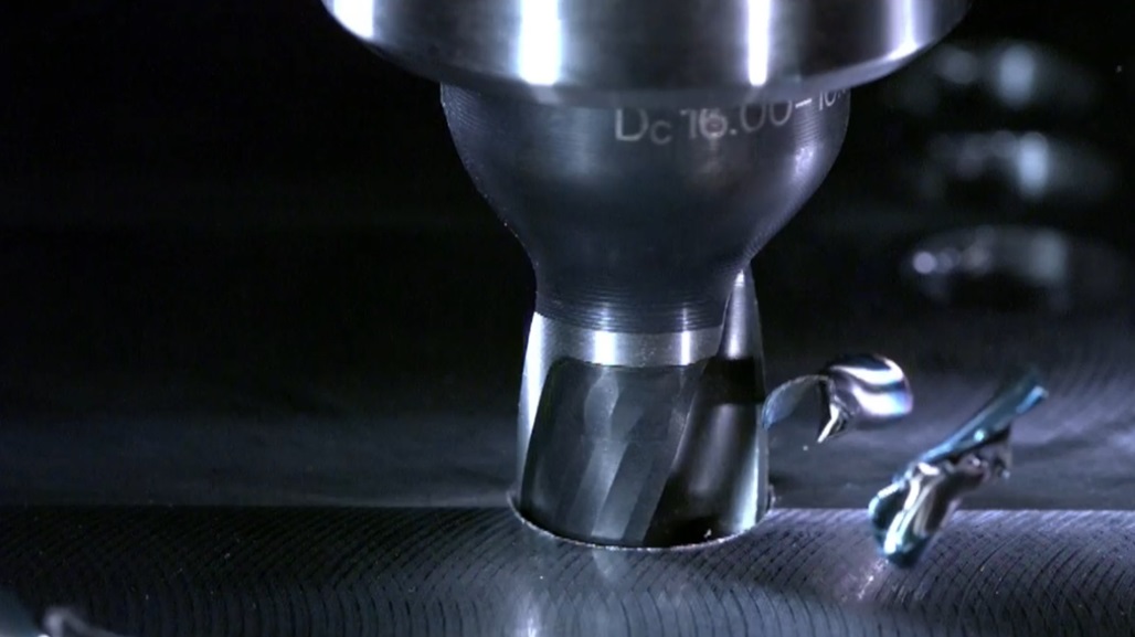
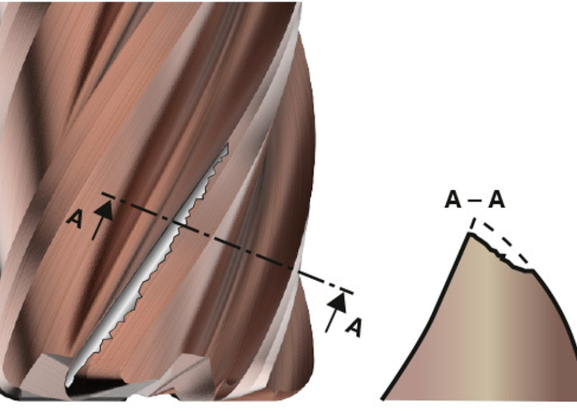
Uniformed flank wear
Example of uniformed flank wear on a solid carbide end mill
Being predictable and dependable, flank wear is the ideal wear pattern you want to see on your tools. Saying that, it shouldn’t happen too quickly as this is considered a problem.
Flank wear is a relatively uniform abrasion along the cutting edge. Occasionally, metal from the workpiece makes it look bigger than it is, but you can expect this kind of wear in all materials and if your tool doesn’t fail by another type of wear, this will be the one to end its life.
Actions you could take:
Increase the coolant concentration
Check and balance the feed rate with the type of flank relief
Check if the balance of cutting speed and feed is correct
Verify that the tool is the best choice for the material
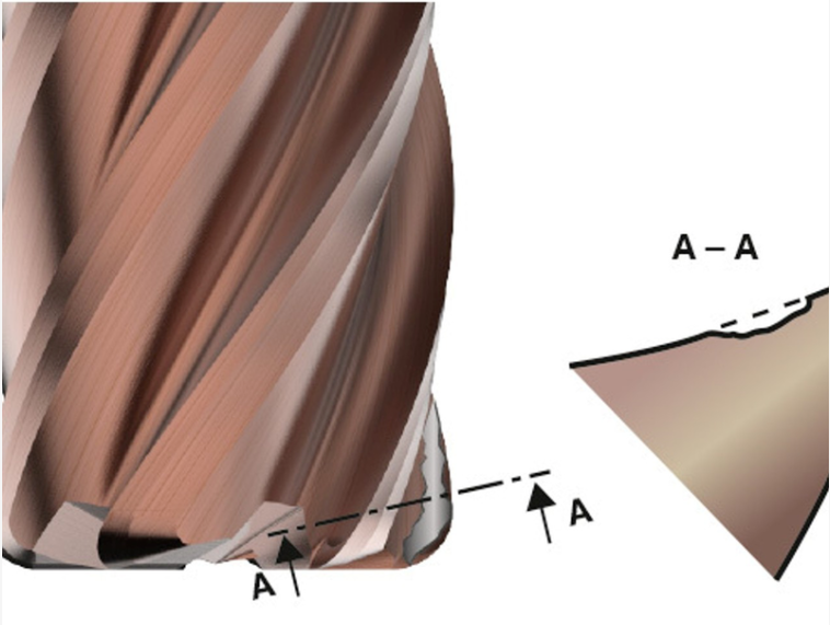
Crater wear
Example of crater wear on a solid carbide end mill
Although not that common in milling operations, crater wear is a combination of heat damage, material breakdown and abrasive wear. And if you want a more technical explanation – the heat from the chips decomposes the tungsten carbide grains in the substrate and carbon leeches into the chips (diffusion), wearing a crater on the rake face of the tool.
Actions you could take:
Increase coolant concentration
Balance the feed rate with the type of rake relief
Check if the balance of cutting speed and feed is correct
Verify that the tool is ideal for the material
There is a more specific type of crater wear called point cratering. This wear pattern is caused by the erosion of a localized area on the cutting edge. It is caused by a combination of chemical reactions and a lot of heat and abrasion from the formed chip.
Actions you could take:
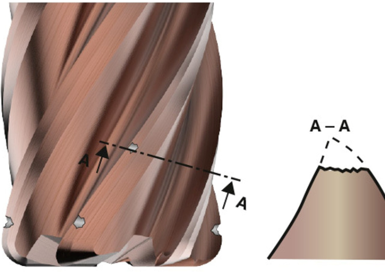
Chipping
Example of chipping on a solid carbide end mill
Chipping is basically a fracturing of the cutting edge. It is typically associated with stability problems and vibrations.
Actions you could take:
Keep the tool length as short as possible
Make sure your set-up is rigid
Check that the tooling is balanced and run-out is within specification
Confirm the cutting parameters are correct
Make sure the tool is suited to the material
Ensure the chips are being evacuated properly
There is a specific type of chipping called point chipping. Mostly associated with stability issues but can also appear when chatter occurs if, for example, the milling strategy isn’t appropriate.
As well as going through all the troubleshooting steps above, you can also:
Check the cutting parameters, as low cutting speeds will lead to chatter
When machining corners, use the trochoidal milling method
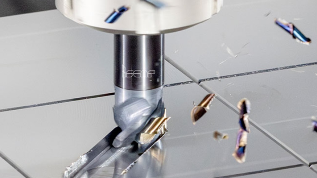
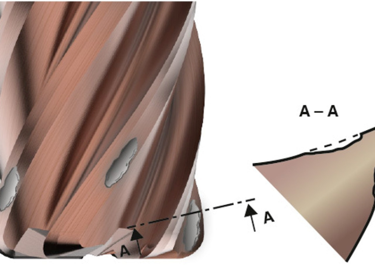
Built-up edges
Example of wear due to built-up edges on a solid carbide end mill
A built-up edge is formed when the workpiece material sticks to the rake face of the milling cutter. Often, the material deposited on the tool’s surface can be caused by pressure, friction and/or inadequate cutting conditions.
Actions you could take:
Increase the cutting speed
Increase the coolant concentration and volume
Use a tool suited to the material – flute design, helix, coating and surface condition are important
Continue reading this blog in its entirety here to learn about other tool wear patterns and actions you can take to mitigate them.
This article was previously featured on Seco Tools' blog.

![The History of Manufacturing in the U.S. [Infographic]](https://images.ctfassets.net/5j4ln2up7bt7/fDsTnKF6GUAIvHgfShnVa/85e0c4f78c822db6b183aef86e779d38/Image_FOUR_GettyImages-1026499496-thumb.jpg)