Tool wear in machining limits tool life, which affects part quality and company costs. MSC’s Dr. Tony Schmitz describes wear mechanisms and testing to model the tool wear rate.
Wear mechanisms in metal cutting include abrasion, adhesion, diffusion and attrition. They combine to form characteristic wear features on cutting tool surfaces.
Tool wear rates depend on cutting tool materials, coatings applied to wear surfaces, and cutting speed.
Tests to measure the flank wear width (FWW) can be used to determine maximum cutting speed to achieve desired tool life.
Tool wear in machining is the progressive deterioration of a cutting tool’s edge. This degradation results in geometric changes to the tool, higher cutting forces and declining part quality, including poor surface finish and dimensional errors.
Tool wear in machining leads to finite tool life, which is often measured in minutes rather than hours. Because tool costs can be significant, selecting a process plan that limits tool wear to an acceptable, predictable level is an important activity for part production by machining. Tool wear is driven by:
High temperatures at the tool-chip interface, which can lead to softening of the tool material
Intimate contact between the chip and tool rake face, which encourages diffusion between the chip and tool materials, particularly at high temperatures; this can cause the carbon-hungry steel chip to rapidly wear an uncoated tungsten carbide cutting tool, for example
Hard inclusions in the workpiece material, which can abrade the tool material
Large cutting forces and pressures, which can cause plastic deformation and fracture of the tool edge
Thermal cycling in interrupted cuts, which can cause cracking and catastrophic tool failure due to thermal fatigue
Primary Tool Wear Mechanisms
Several wear mechanisms have been identified in metal cutting. These include abrasion, adhesion, diffusion and attrition.
Abrasion
Abrasion occurs when hard particles in the workpiece material scratch the tool surface as the chip is sheared away. It can also occur when small particles of the hard tool material are dislodged and carried away with the chip, again scratching the tool surface. The hard particles can be carbides, oxides or nitrides, for example.
Adhesive Wear
Adhesive wear occurs when the work material locally welds to the tool surface due to high temperatures and pressures, then tears away tool material as it is removed during the chip formation process. Adhesion is also the mechanism for built-up edge (BUE), which is typically observed at lower cutting speeds. BUE occurs near the tool point where the tool-chip interface temperature is lower and the harder material tends to seize against the tool rake face. Farther along the contact, the temperature is higher and the softer chip slides more easily. The BUE can change the effective rake angle at the tool point, which affects the cutting force magnitude.
Diffusion
Diffusion depends on the chemical affinity between the tool and workpiece. Its rate, which is defined by the number of atoms of the tool or workpiece material that penetrates the other at the intimate, high-pressure rake face contact, is strongly temperature dependent, so diffusion often dominates at high cutting speeds where the tool-chip interface temperature is also high. Diffusion is therefore a mechanism for crater wear, which occurs where the temperature is highest, although adhesion and abrasion can also contribute to crater development. Additionally, diffusion participates in flank wear.
Attrition
Attrition occurs when tool material grains near the cutting edge are broken out by contact with the chip and machined surface. It is a primary mechanism for flank wear and can dominate at low cutting speeds with nonuniform chip flow.
Common Wear Features on Cutting Tools
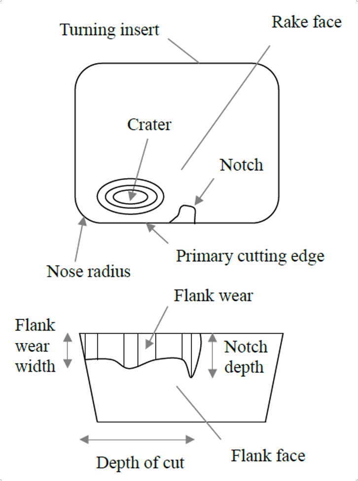
These wear mechanisms combine to form characteristic wear features on cutting tool surfaces. Common wear features include flank, crater and notch wear. These are depicted in Fig. 1. In many cases, a single wear feature will dominate, but all may occur simultaneously.
Figure 1: Common wear features in metal cutting.
Key Factors That Influence the Tool Wear Rate
The tool wear rate depends on the cutting tool material and any coatings applied to the wear surfaces. Fundamental tool material requirements include:
A higher hardness than the work material at the cutting temperature
High strength to resist cutting stresses
High toughness to avoid fracture under impact loads
Low reactivity (chemically inert, for example)
Tool materials have progressed from high-speed steels in the 1900s to sintered carbides, such as tungsten carbide (WC) and titanium carbide (TiC) in the 1930s, to ceramics, such as Al2O3, cubic boron nitride (CBN) and polycrystalline diamond (PCD) in the 1960s, and coated steels and carbides in the 1970s. Coatings are applied by chemical vapor deposition (CVD) and physical vapor deposition (PVD). Common examples include TiC, TiN, Al2O3 and combinations of these in alternating layers. One important issue for coating life is the cutting edge preparation. Edge honing can be used to increase the coating persistence at the sharp edge. It can also increase the process damping effect, where increased stable axial depths of cut are made available at lower spindle speeds.
Although it has been understood since the early 1900s that the rate of tool wear depends strongly on the cutting speed, as well as other process parameters, and tool geometry, its preprocess prediction remains elusive. Empirical modeling efforts are therefore common. In tool life testing, we begin with a new cutting edge, machine for a selected time or volume of material removed, and measure the flank wear width (FWW) or other features after that interval. We then continue the test for a second interval and remeasure. This process is repeated until the tool reaches the FWW limit. This sequence is repeated using different sets of process parameters to determine the best-fit constant(s) for a power law-type tool life equation. The ranges for the experimental process parameters may be based on tool supplier recommendations or prior experience, for example.
Tool Life Testing and Results: Modeling the Tool Wear Rate
To demonstrate the procedure for identifying an empirical tool life model, let’s examine experimental results from a milling study. Tool wear tests were completed using a 19.1 mm diameter, single-insert indexable endmill (uncoated carbide) to machine 1018 steel. The tool life model was vT^n = C, where v is the cutting speed, T is the time to reach the preselected FWW limit, and n and C are empirical constants. A digital microscope was mounted to the machine table and used to measure the FWW on the carbide insert at intervals of 12 cm^3 of volume removed (no significant crater or notch wear was observed). The milling parameters were: radial depth of 4.76 mm (25 percent RI), axial depth of 3 mm and feed per tooth of 0.06 mm.
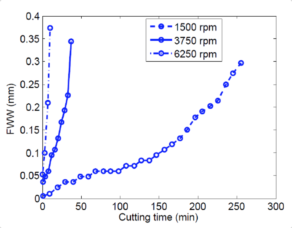
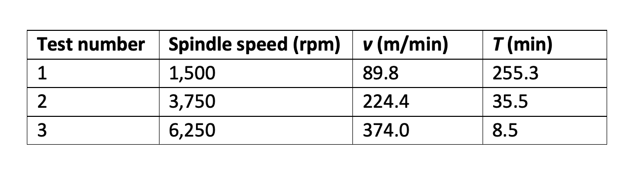
The FWW progressions for tests at spindle speeds of 1,500 rpm, 3,750 rpm and 6,250 rpm are shown in Fig. 2. The tool life was defined as the time required to reach a FWW of 0.3 mm. As expected, the tool life decreased with the increased cutting speed (and temperature). The test results are summarized in Table 1.
Figure 2: FWW versus cutting time for all three spindle speeds. The tool wear rate increases rapidly with increasing spindle speed.
Table 1: Test results for milling 1018 steel with an uncoated carbide insert.
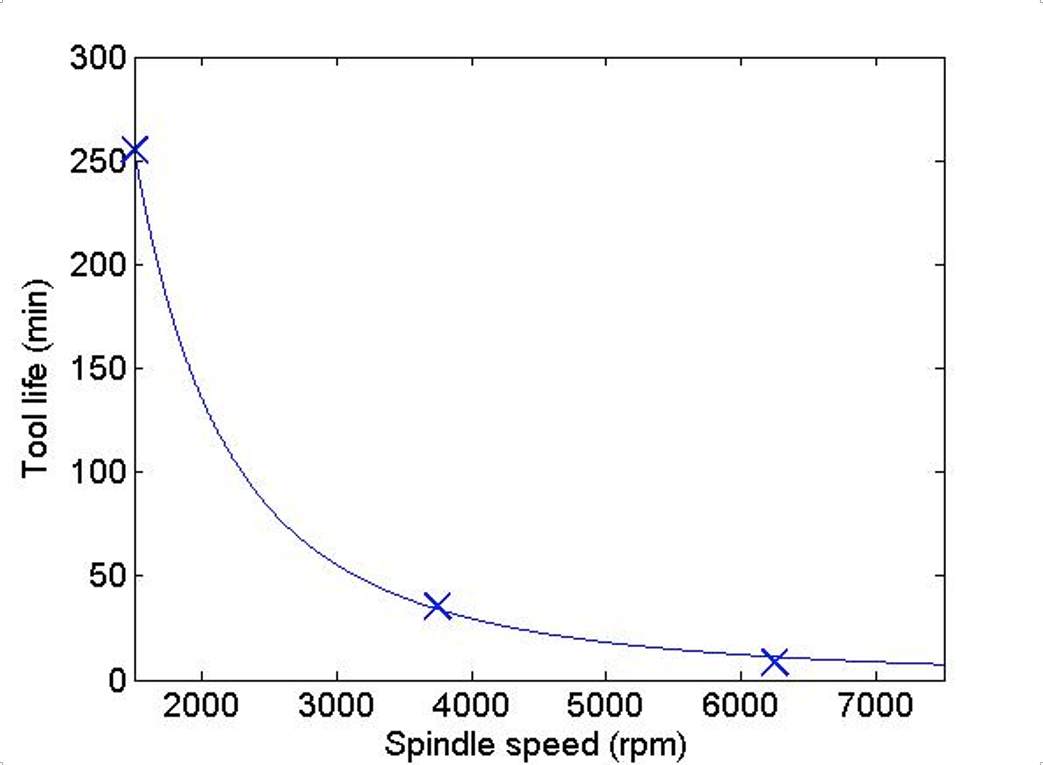
The tool life model constants were determined from a least-squares best fit to the data: vT^(0.455) = 1,120. The data points and fit are presented in Fig. 3. Given this model, a spindle speed may be selected to give the desired tool life. For example, if a tool life of 60 minutes is desired, the spindle speed should be 2,800 rpm or lower in this case.
Figure 3: Tool-life model (solid line) and experimental data points (x) for 1018 steel tool wear tests.
Parts of this article appeared in the ebook Machining Dynamics (2019) and the Journal of Manufacturing Science and Engineering (2020) by Tony Schmitz.
Dr. Tony Schmitz is a distinguished technical fellow at MSC who offers a rare blend of deep academic rigor and real-world manufacturing insight. He has a Ph.D. in mechanical engineering and more than 25 years of experience in machining dynamics, vibration, metrology and advanced manufacturing. He has authored more than 200 peer-reviewed papers as well as three engineering textbooks, and he holds 12 U.S. patents.
To request a quote, please login to your existing account or register a new one. This helps us provide you with a personalized experience and keep track of your requests.