Moving Past Speeds and Feeds to Master the Physics of the Cut
There is a specific point of frustration that every machinist eventually hits on the lathe. The job is dialed in, the speeds and feeds are theoretically perfect, and the coolant is hitting the sweet spot; yet the cut still isn’t right. You might see inconsistent tool life, a subpar surface finish, or unexplained insert failure. Usually, the first instinct is to tweak the parameters by backing off the surface footage or fine-tuning the feed rate. However, if those adjustments don’t yield results, you are likely chasing your tail because the problem isn’t in the numbers. It is rooted in the insert geometry.
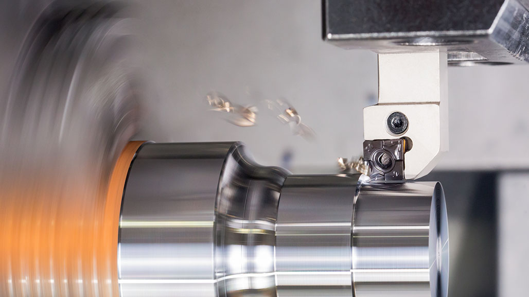
The Mechanical Reality of Chip Control
If your parameters are correct but the cut feels wrong, you are likely fighting the chip rather than the material. Geometry is the mechanical engine that forces the material to curl, fracture, and evacuate. When an insert “birdsnests,” it is often because the chipbreaker geometry is not matched to your depth of cut. If the chip does not engage the insert geometry with enough force, it will not snap. This is why a “Medium” geometry insert often fails in a light finishing pass. It is not because the speed is wrong, but because there is not enough material volume to engage the chip breaking features. Stabilizing a process requires matching the insert geometry to the specific volume of metal you are moving.
Choosing the Right Foundation: Insert Shape
This stabilization starts with the structural footprint of the tool. Choosing an insert shape is a constant trade-off between accessibility, strength, and economics. Sharp, open shapes like 35 degree V-style (VNMG) or 55 degree D-style (DNMG) inserts are mandatory for profiling, but they are structurally weak and offer fewer usable edges. Conversely, closed shapes like 80 degree C-style (CNMG) or Square (SNMG) inserts distribute cutting pressure across a larger foundation. While the SNMG is a staple in many shops for its economy, offering up to eight usable cutting edges, its real benefit is combining that cost-efficiency with extreme predictability under heavy roughing loads. When part geometry allows, SNMG inserts can be a great option. For even better economy, consider keeping a tool holder on hand that utilizes the 100-degree edges of your CNMG inserts for rough facing and turning. This improves both edge strength and your overall cost per part.
Watch now: You're Scrapping Turning Parts...It's NOT Speeds & Feeds
Managing Forces with Positive vs. Negative Rakes
Once you have the right shape, you have to decide how that edge meets the part. This is not just a choice between sharp or dull; it is about how forces are applied to the machine and the workpiece. Positive geometries like CCMT’s act like slicing with a sharp knife. It reduces cutting forces, making it the standard choice for Swiss-type machines, small diameter boring, and gummy materials. Conversely, inserts with negative geometry like CNMG’s act more like a wedge, requiring more horsepower and rigidity, but adding a massive amount of strength to the cutting edge. Because the 90-degree edge is supported by a significant volume of carbide, it can withstand the extreme pressures of heavy-duty machining. Furthermore, since negative inserts are typically double-sided, they offer twice the cutting edges of a positive insert, making them the industrial standard for high-volume, heavy-duty roughing.
Directional Control: The Power of Lead Angle
Lead angle is one of the most effective tools for managing force distribution, yet it is often the most ignored. A steep lead angle concentrates all the impact stress and pressure into one localized spot on the edge. This is the primary cause of notching at the depth of cut line, particularly in work-hardening materials like stainless or Inconel. By reducing the lead angle, you spread that same cutting load across a longer section of the carbide. This thins the chip and improves heat dissipation, allowing for higher productivity without overstressing the tool. However, shifting the lead angle also shifts the direction of the force, which can introduce vibration if your tool post or part stick-out lacks rigidity.
Precision at the Point: Nose Radius and Wipers
The nose radius is the final gatekeeper of part quality and setup stability. A larger radius strengthens the weakest part of the insert and improves finish potential, but it generates more radial force. This pressure actively tries to push the part away from the tool, which can lead to taper on long shafts and chatter on thin-walled parts. As a practical guideline, your depth of cut should generally stay deeper than the nose radius to ensure proper chip formation. If you need to increase finish quality without compromising on feed rate, Wiper Geometry is the solution. A wiper flat smooths the surface over a wider contact area. This allows you to achieve the same surface finish at twice the feed rate or half the surface roughness at the same feed rate. If you are fighting chatter or vibration but still need a good surface finish, consider down-sizing the nose radius and trying a wiper geometry. Using a smaller nose radius, even with the wiper flat, can still reduce cutting pressure, while the wiper will often allow for better surface finishes than a larger radii standard insert.
The Bottom Line: Geometry is the Governor
Ultimately, insert geometry does not fail in a vacuum; it fails relative to the rigidity of your setup. Every choice you make, from an eight-edged SNMG to a productivity-boosting wiper flat, is a negotiation with the machine’s ability to hold a line. If the geometry is fighting the physics of the cut, no amount of dial-turning will save the part. Evaluate the shape for strength, the rake for pressure, the lead angle for heat, and the chipbreaker for control. When you align these variables into a single system, you stop guessing and start machining. Get the physics right, and the numbers will follow.
This article was previously featured on Kyocera's blog.