Cutting force in milling affects part quality and process stability. MSC’s Dr. Tony Schmitz breaks down the force model and how manufacturers can use it to predict and eliminate chatter.
Chip thickness variability is the root cause of force fluctuation.
Radial immersion and milling direction fundamentally shape the force profile.
Down milling’s chip-thinning behavior makes it preferable for finishing.
The cutting force model is the foundation for chatter prediction.
Understanding the forces acting on a cutting tool during milling is essential for optimizing machining parameters and achieving consistent, high-quality results.
How Chip Thickness Drives Cutting Force Variation
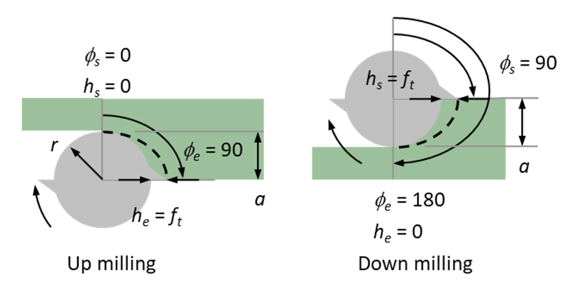
The cutting force in milling can be modeled using the process geometry. The milling force varies because the chip thickness varies, even in the absence of tool or workpiece vibrations. Fig. 1 shows this variation for both conventional (up) and climb (down) milling operations. Note that the chip thickness increases with tool rotation during up milling and decreases during down milling. For the latter, we refer to this as chip thinning.
The entry, or start, angle for up milling is Øs = 0, while the exit angle, Øe, depends on the radial depth of cut, a, and tool radius, r, as shown in Eq. 1.
For down milling, the exit angle is Øe = 180 deg. Like up milling, the start angle is calculated using the radial depth and tool radius. See Eq. 2.
Figure 1: Start and exit angles and corresponding chip thickness, h, variation for up and down milling (a = r, or 50% radial immersion) [1].
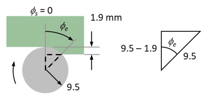
Consider the up milling cut shown in Fig. 2, where the radial depth of cut is 1.9 mm. For a 19 mm diameter (9.5 mm radius) tool, this is a 10% radial immersion cut. Because it is up milling, the start angle is Øs = 0. The exit angle is:
and the instantaneous chip thickness, h, between the start and exit angles is defined by Eq. 3, where ft is the feed per tooth. The chip thickness starts at zero and ends at 0.09 mm if the feed per tooth is 0.15 mm. Because the exit angle is less than 90 deg, the chip thickness never reaches the commanded feed per tooth value.
Figure 2: Exit angle for 10% radial immersion up milling cut.
Projecting Cutting Forces into the Machine Tool Coordinate Frame
Because the chip thickness is not constant in milling, the cutting force is not constant. Like the chip thickness in Eq. 3, the cutting force also depends on the tool angle. The complete cutting force model includes the chip thickness variation with tool angle, the number of teeth simultaneously engaged in the cut at any instant, and the projection of the cutting force into the machine tool coordinate frame. We express the cutting force on any tooth as a function of the chip area, A, and specific force, Ks; see Eq. 4, where b is the axial depth in milling and Ks depends on the workpiece material and tooth geometry (e.g., rake angle).
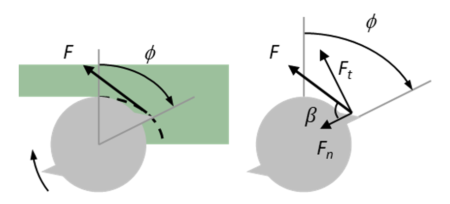
Figure 3: Cutting force geometry for milling.
The normal, n, and tangential, t, components of the cutting force are written using Eqs. 5 and 6 and are displayed in Fig. 3, where β is the cutting force angle relative to the normal direction.
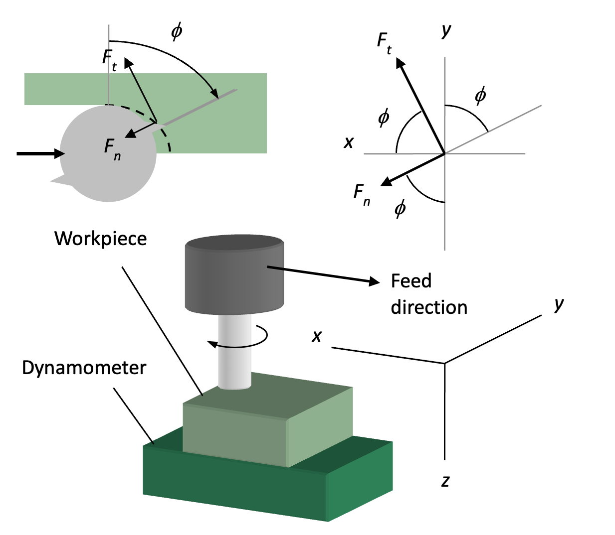
The single tooth force shown in Fig. 3 is described in a coordinate frame that rotates with the tool. For measurement purposes, however, it is convenient to express the force in the machine tool’s coordinate frame. For example, the workpiece may be mounted on a cutting force dynamometer and the x, y and z direction force components recorded during milling; see Fig. 4. To model these forces, we must project the normal and tangential components into the x and y directions using the tool angle. Generally, we can neglect the z direction component along the tool axis because the tool stiffness is much larger in this direction than x and y. See Eqs. 7 and 8.
Figure 4: Geometry for projecting the tangential and normal cutting force components into the x and y machine tool coordinate directions.
Using Force Models to Predict and Prevent Chatter
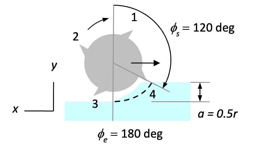
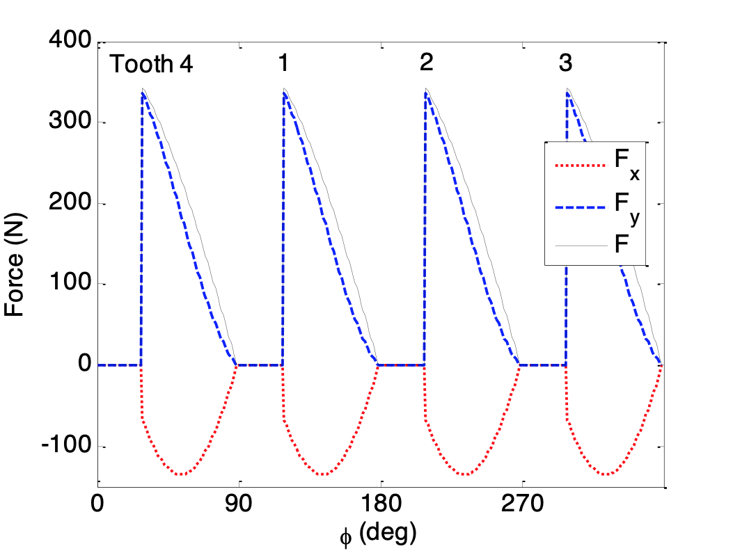
Let’s conclude with an example calculation of cutting force components for down milling. Fig. 5 shows the geometry for a 25% radial immersion down milling cut. Fig. 6 displays the single revolution cutting force profile for kt = 750 N/mm2 and kn = 250 N/mm2 (corresponds to Ks = 791 N/mm2 and β = 71.6 deg; these values are representative of an aluminum alloy), b = 5 mm, and ft = 0.1 mm. The starting angle is:
and the exit angle is Øe = 180 deg. We see that tooth 4 enters the cut first (assuming a start angle of Ø = 0 when tooth 1 is vertical). This entry occurs after a 30 deg delay where no cutting occurs (i.e., the 90 deg lead of tooth 4 relative to tooth 1 plus 30 deg gives the 120 deg cut starting angle). The maximum force level is encountered at 30 deg and then decreases with the chip thickness to an angle of 90 deg; this trend of force reduction as the final surface is being created explains why down milling is often selected for finishing passes when surface finish is most critical. After Ø = 90 deg is reached, the force is again zero until tooth 1 enters the cut at 120 deg and the cycle is repeated. The negative x direction force means that it is acting to the right in Fig. 5.
Figure 5: 25% radial immersion down milling geometry.
Figure 6: 25% radial immersion down milling cutting force components.
Finally, the periodic, impulsive nature of the cutting force in Fig. 6 is effective at exciting the tool-holder-spindle-machine structural dynamics. The outcome is vibration that can either be stable or unstable (chatter). Given the force model and the tool tip vibration response (described using the frequency response function, or FRF), we can generate a stability map that enables us to select chatter-free milling parameters without the need for trial-and-error testing.
References
Schmitz, T. and Smith, K.S., 2019. Machining Dynamics: Frequency Response to Improved Productivity, Second Edition. Springer.
Dr. Tony Schmitz is a distinguished technical fellow at MSC who offers a rare blend of deep academic rigor and real-world manufacturing insight. He has a Ph.D. in mechanical engineering and more than 25 years of experience in machining dynamics, vibration, metrology and advanced manufacturing. He has authored more than 200 peer-reviewed papers as well as three engineering textbooks, and he holds 12 U.S. patents.
To request a quote, please login to your existing account or register a new one. This helps us provide you with a personalized experience and keep track of your requests.