Digital Readout (DRO) Systems Technical Information
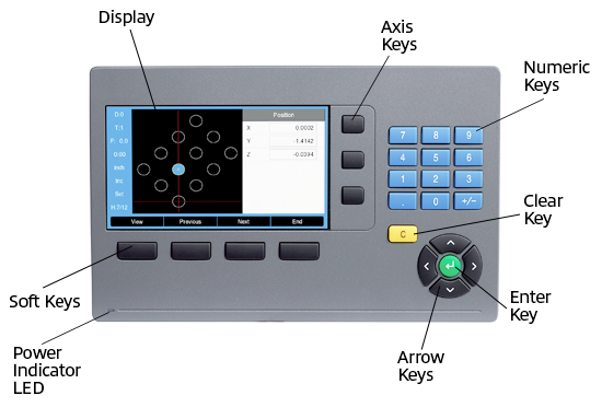
Digital Readout (DRO) Systems display the position of a cutting tool relative to the workpiece using encoders mounted on each axis. Equipped with a numeric display and keyboard, DROs are commonly used on milling machines, lathes, boring machines, and surface grinders.
Encoder Defined
Encoders are sensors that electronically capture data like count, direction, position, and speed. Paired with a glass linear scale, they convert physical movement into digital signals, which are sent to a machine for processing and application-specific use.
Measuring for a DRO
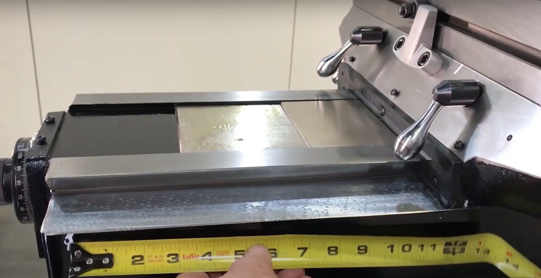
The overall length of a scale refers to the total space it occupies, while the measuring length indicates the distance it can accurately measure along the axis. These two dimensions are distinct and should not be confused. To measure the correct travel length for the X, Y, and Z axes, first use a tape measure to assess the available space for encoder installation. Then follow the steps below to determine the usable measuring length. Ensure this length is shorter than the machine’s hard stops to prevent encoder damage.
- X-Axis (Right to Left): Move the table fully to the left and mark a reference point between the table and the stationary saddle. Then, move the table fully to the right and measure the distance from the mark to the right edge of the saddle. Doing this gives you the total travel distance.
- Y-Axis travel (Front to Back): Move the table fully forward and mark a reference point between the machine base and the stationary saddle. Then, move the table fully back and measure the distance from the mark. This gives you the Y-axis travel length.
- Z-Axis travel (Up and Down): Measure the total distance traveled by the quill to determine Z-axis travel.
- W-Axis travel (Up and Down – Typically for Knee Mills): Move the table to its lowest position and mark a reference point between the table and the stationary saddle. Then raise the table to its highest position and measure the distance from the mark. This gives you the W-axis travel.
Essential Tip:
Some digital readout systems can display a 4th axis on a knee mill—typically the W-axis. It may be shown separately or electronically linked with the quill to represent total Z-axis movement.
Scales
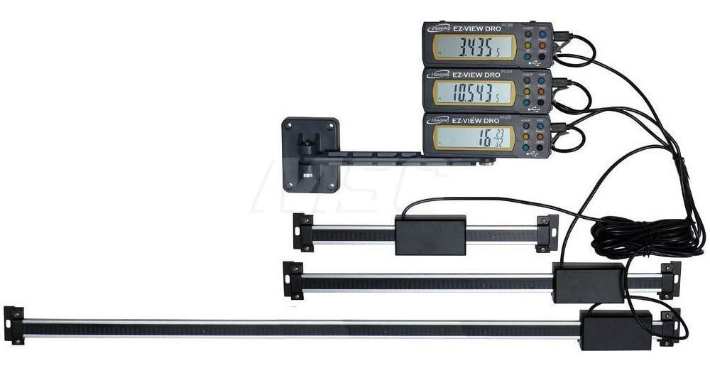
Digital readout linear scales capture movement data and convert it into digital signals, which the encoder sends to the DRO. They are typically made from precision glass or use inductive or magnetic technology.
Glass scales are used in precision applications due to their stability in size, shape, and density. They work by allowing evenly spaced light to pass through, creating a pattern detected by a photoelectric sensor that generates signals for the DRO. While offering good protection against dirt and coolants, they remain vulnerable to contamination. Glass scales are also more economical than magnetic ones.
Inductive or magnetic scales are durable and resistant to coolants, liquids, and dirt. With a smaller cross-section than glass scales, they’re ideal for machines with limited space. These scales measure changes in induced or magnetic energy, converting them into electrical pulses read by the DRO. Additionally, magnetic scales can be cut to any length.
Travel
DRO systems are designed to monitor multiple axes:
- 2-axis systems track X and Y axes
- 3-axis systems track X, Y, and Z axes
- 4-axis systems track X, Y, Z and W axes
X-axis travel, or Longitudinal Travel, is the maximum horizontal distance the working surface moves from right to left.
Y-axis travel, or Cross Travel, is the maximum distance the working surface moves forward and backward (in and out).
Z-axis travel, or Quill Travel, is the maximum vertical distance the quill can move up and down.
W-axis travel, or Knee Travel, is the maximum vertical movement of the working surface, typically found on knee milling machines.
Digital Readout Equipment from MSC Industrial Supply
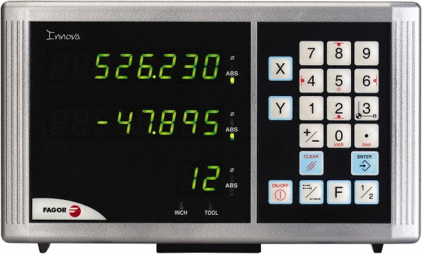
DRO Counters display data collected by the scale and encoder, showing measurements in inches, millimeters, degrees, or RPM.
DRO Brackets & Mounting Hardware - including bracket kits, mounting arms, and pivot assemblies - are available from MSC. Choose the accessories that best fit your DRO system.
To request a quote, please login to your existing account or register a new one. This helps us provide you with a personalized experience and keep track of your requests.