Tech Essentials High Performance Taps
High-performance taps are designed to cut precise, reliable threads in tough materials and high-volume production. Whether you’re cutting stainless steel, nickel alloys, titanium, or softer metals like aluminum and brass, these taps combine premium steels, advanced geometries, and specialized coatings to maintain consistent performance and keep the cost per part low.
Modern designs minimize torque, reduce heat, and improve chip evacuation. Many CNC-ready taps feature necked designs that channel coolant directly to the cutting edges, helping the tool run cooler and last longer in both high- and low-volume applications.
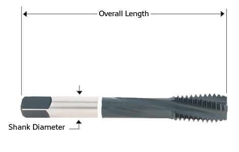
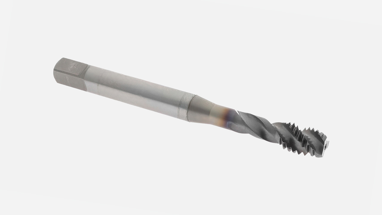
Diagram of a High-Performance Tap
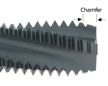
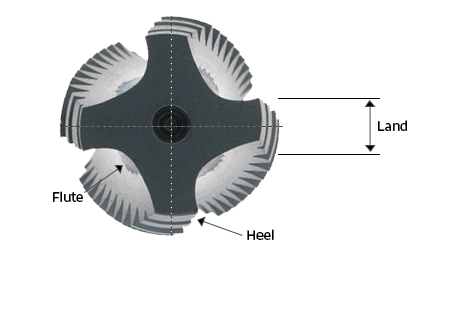
Flutes, Threads & Chamfers
Types of High-Performance Taps
Spiral Point Taps
Designed for through holes. Their geometry pushes chips forward, reducing clogging and allowing faster, more reliable cutting.
Spiral Flute Taps
Best for blind holes in aluminum, brass, and softer steels. The spiral pulls chips up and out of the hole to prevent jamming.
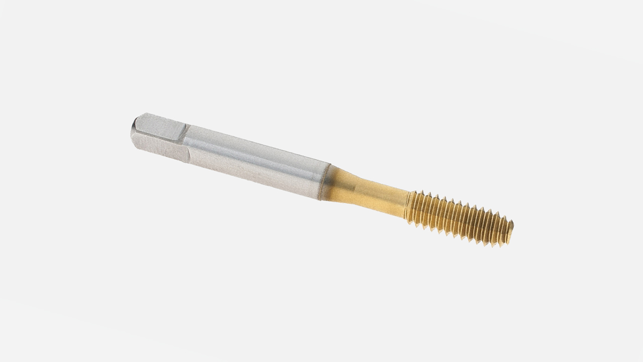
Thread Forming Taps
Thread forming taps don’t cut- they displace material to create stronger threads without chips. This makes them ideal for carbon steels, mild steels, and low- to medium-strength alloys.
Chamfer Styles
Chamfer style refers to the number of tapered threads at the front of the tap. This taper distributes cutting forces and controls how the tap starts in the hole. The style you choose depends on whether you’re threading a through hole or a blind hole.
Taper Chamfer
7–10 threads tapered
Provides the easiest starting action with less cutting force
Best for hand tapping and through holes
Plug Chamfer
3–5 threads tapered
General-purpose style, suitable for most tapping applications
Balances cutting ease with depth capability
Bottoming Chamfer
1–2 threads tapered
Used when threads must extend as close as possible to the bottom of a blind hole
Requires more torque to drive, often used after starting with a plug tap
Class of Fit
Class of fit defines how tight or loose a threaded connection will be, ensuring the tap produces the correct tolerance.
Unified Threads (inch): “A” = external threads (screws, bolts), “B” = internal threads (tapped holes).
Metric Threads: “G” = external threads, “H” = internal threads.
Common Classes and Applications
Class 1A / 1B: Loose fit, used where quick or frequent assembly is needed.
Class 2A / 2B: The most common class. Medium fit that balances strength with ease of assembly. Found in most screws, bolts, and nuts.
Class 3A / 3B: Tight, precision fit. Used when accuracy is critical. Parts are typically gauged to verify fit.
Thread Limits (H & D)
Thread limits provide fine-tuned control over the size of a tap, helping ensure the finished threads meet the required class of fit. Selecting the right H or D limit ensures your high-performance tap produces threads that meet application requirements while maximizing tool life. Limits are marked with:
“H” for inch taps
“D” for metric taps
Each number (H1, H2, H3, etc.) represents a slightly larger tap size. This allows you to adjust the thread fit depending on whether you need a tighter or looser tolerance.
For taps up to 1" diameter, each step adds +0.0005".
For taps over 1" diameter, each step adds +0.001".
Rule of thumb: Always choose the largest H-limit that still meets the required class of fit. This ensures accuracy while extending tool life.
Common Ranges of Thread Limits
H1 / D1 →Tightest fit (basic +0.0005"–0.0010")
H2 / D2 →Standard fit for most production tapping (basic +0.0005"–0.0010")
H3 / D3 through H5 / D5 →Slightly looser fits for tougher materials or when taps wear quickly
H6 / D6 and above →Progressively looser fits, used when threads risk binding or when longer tool life is prioritized
Thread Limit (H & D) Cross Reference Guide
H1 /D1 | Basic plus .0005" - .0010" |
H2 /D2 | Basic plus .0005" - .0010" |
H3 /D3 | Basic plus .0010" - .0015" |
H4 /D4 | Basic plus .0015" - .0020" |
H5 /D5 | Basic plus .0020" - .0025" |
H6 /D6 | Basic plus .0025" - .0030" |
H7/D7 | Basic plus .0030" - .0035" |
H8/D8 | Basic plus .0035" - .0040" |
H9/D9 | Basic plus .0040" - .0045" |
H10/D10 | Basic plus .0045" - .0050" |
H11/D11 | Basic plus .0050" - .0055" |
H12/D12 | Basic plus .0055" - .0060" |
Standard Tap Materials
Tap performance begins with the base material. Different steels provide varying levels of toughness, heat resistance, and wear life.
High Speed Steel (HSS)
Most common tap material
Provides good toughness at a low cost
Best for general-purpose threading in low-strength steels, aluminum, and non-ferrous materials
Cobalt (HSS-E)
HSS enhanced with cobalt for increased hardness and heat resistance
Performs well in stainless steels, titanium, and tougher alloys
Handles higher cutting speeds than standard HSS
Powdered Metal (PM)
Stronger and tougher than HSS, less brittle than carbide
Excels in abrasive materials like high-silicon aluminums
Good balance of cost and performance in production settings
Solid Carbide
Extremely hard and wear-resistant
Ideal for high-speed CNC applications in hardened steels, nickel alloys, and aerospace materials
Best choice for precision, high-volume production where tool life is critical
Standard Finishes
Standard tap finishes improve chip flow, reduce friction, and support longer tool life across different materials.
Bright (Polished)
Smooth finish enhances chip evacuation
Commonly used for aluminum, brass, and plastics
Oxide (Black Oxide)
Improves lubrication and reduces galling
Well-suited for ferrous metals, stainless steel, and low-carbon steels
Chrome Plate
Adds a low-friction, corrosion-resistant surface
Common in steel, aluminum, brass, and copper
Nitride
Thin, hard surface treatment
Increases wear resistance in abrasive applications
To request a quote, please login to your existing account or register a new one. This helps us provide you with a personalized experience and keep track of your requests.