Lathe chucks are workholding devices used to accurately clamp a workpiece on a lathe for turning operations. They can also be used on an indexing fixture for milling.
Lathe Chucks: Clamp, Center, and Control Your Work
Learn how different lathe chucks work, compare jaw designs, and understand spindle mounting options.
Lathe Chucks
1. Manual lathe chucks manually open or close jaws with a screw or pinion.
2. Power lathe chucks use hydraulics, pneumatic, or electricity to close the jaws. They provide high gripping accuracy and are designed for mass production.
Lathe Chuck Body Materials
Lathe Chuck Spindle Types
To determine which type of spindle nose mounting your lathe requires, consult the diagrams and general measurement information.
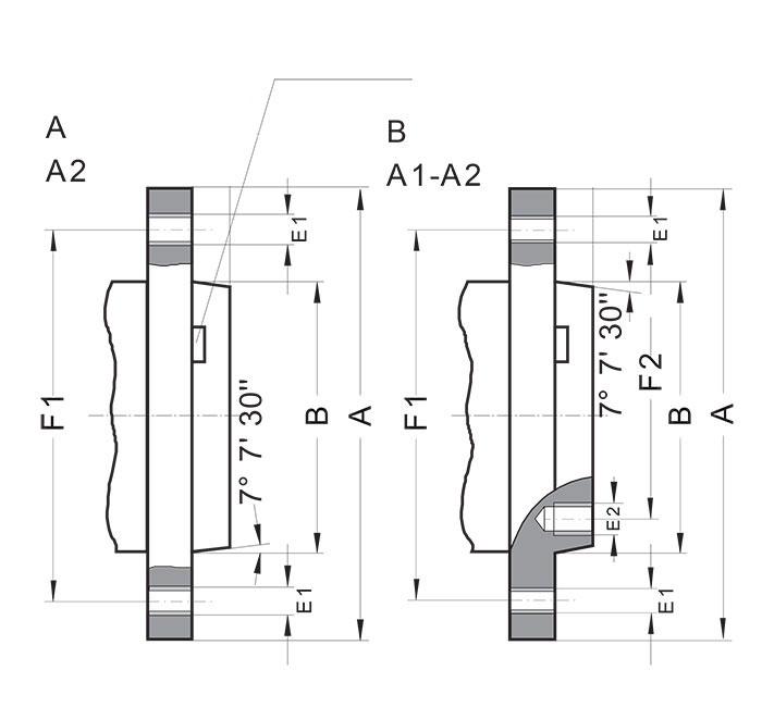
American Standard “A” Series Spindle
Type A: Tapped holes in the flange, no inner bolt circle.
Type B: Tapped holes in the flange and inner bolt circle.
Spindle nose size | B max. [in] | E1 (UNC-3B) | F1 [in] | E2 (UNC-3B) | F2 [in] |
|---|---|---|---|---|---|
3 | 2.13 | 7/16-14 | 2.78 | 7/16-14 | - |
4 | 2.50 | 7/16-14 | 3.25 | 7/16-14 | - |
5 | 3.25 | 7/16-14 | 4.13 | 7/16-14 | 2.44 |
6 | 4.19 | 1/2-13 | 5.25 | 1/2-13 | 3.25 |
8 | 5.50 | 5/8-11 | 6.75 | 5/8-11 | 4.37 |
11 | 7.75 | 3/4-10 | 9.25 | 3/4-10 | 6.50 |
15 | 11.25 | 7/8-9 | 13.00 | 7/8-9 | 9.75 |
20 | 16.25 | 1-8 | 18.25 | 1-8 | 14.50 |
28 | 23.00 | 1-1/4-7 | 25.50 | 1-1/4-7 | 20.87 |
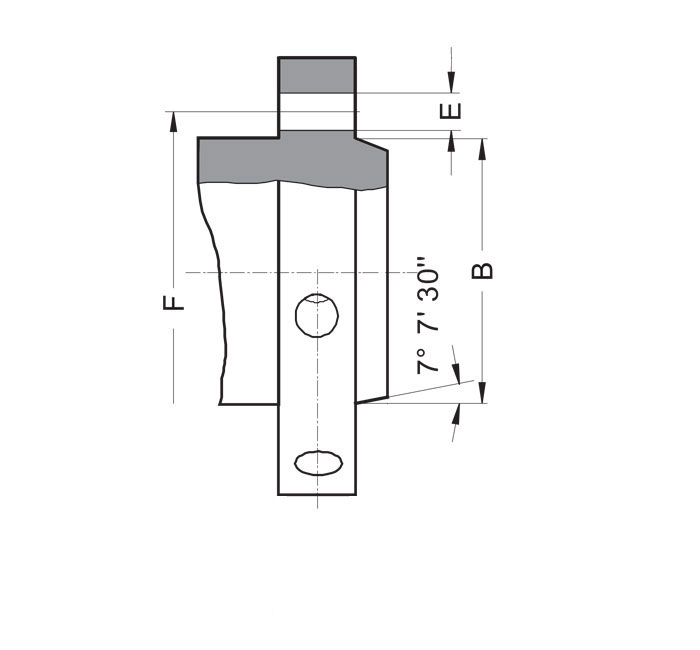
Camlock “D” Series Spindle
Uses cams to lock the chuck into place.
Designed for quick-change chuck installation.
Spindle nose size | B max. [in] | E1 (UNC-3B) | F [in] |
|---|---|---|---|
3 | 2.13 | 3 x 0.59 | 2.78 |
4 | 2.50 | 3 x 0.66 | 3.25 |
5 | 3.25 | 6 x 0.78 | 4.13 |
6 | 4.19 | 6 x 0.91 | 5.25 |
8 | 5.50 | 6 x 1.03 | 6.75 |
11 | 7.75 | 6 x 1.22 | 9.25 |
15 | 11.25 | 6 x 1.41 | 13.00 |
20 | 16.25 | 6 x 1.66 | 18.25 |
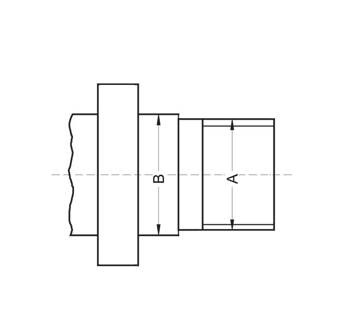
Long Taper Key Drive “L” Series Spindle
Known as the “L” Series.
Uses a taper and key drive for secure mounting.
Spindle nose size A | A. [in] | B. [in] |
|---|---|---|
L00 | 2.750 | 3-3/4" - 6" |
L0 | 3.250 | 4-1/2" - 6" |
L1 | 4.125 | 6" - 6 |
L2 | 5.250 | 7-3/4" - 5" |
L3 | 6.500 | 10-3/8" - 4" |
Threaded Spindle
Threads directly onto the spindle.
Spindle nose size A | B [in] |
|---|---|
1" - 10" UNS-2B | 1.015 |
1-1/2" - 8" UN-2B | 1.515 |
2-3/16" - 10" UN-2B | 2.2025 |
2-1/4" - 6" UN-2B | 2.2600 |
2-3/16" - 6" UN-2B | 2.2025 |
2-3/4" - 8" UN-2B | 2.7600 |
Chuck Types & Their Applications
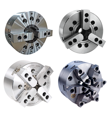
Self-Centering Chucks
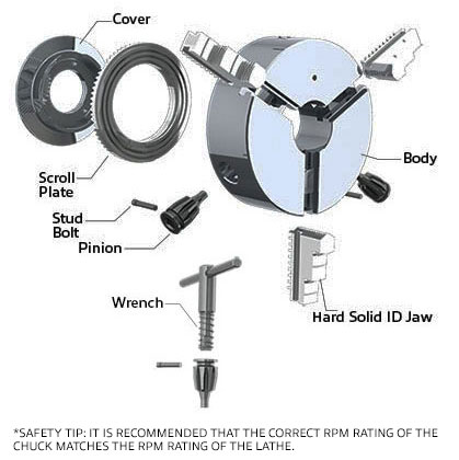
Ideal for gripping cylindrical or concentric work because all jaws work in unison and automatically center the piece. The jaws on the scroll open and close with a wrench that is turned on a pinion.
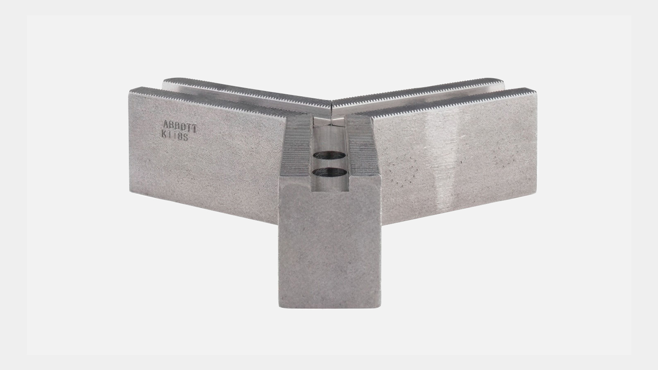
- 2-jaw self-centering chucks: Used for rectangular-shaped parts as a stationary fixture.
- 3-jaw self-centering chucks: Most versatile; ideal for round parts like bars, rings, and pipes.
- 4-jaw self-centering chucks: Used for square parts.
- 6-jaw self-centering chucks: Used for thin-walled parts. More gripping points allow for even distribution of clamping forces and prevention of distortion.
Independent Chucks
- Jaws move independently.
- Best for irregular or eccentric workpieces.
- Longer setup time than self-centering chucks.
Combination Chucks
- Self-centering with individual jaw adjustment allows each jaw to be operated independently or move simultaneously as a self-centering scroll chuck.
- Useful for repeatable centering of irregular parts.
- Individual jaw adjustment also allows for reducing runout on regular jobs.

Chuck Mounting & Spindle Nose
- Direct-mount chucks mount directly on one specific spindle type (e.g., D1-6).
- Plain back chucks require adapter plates to mount on a spindle nose and can be used across different machines.
- Plain back chucks (front-mounting) feature mounting bolts that go from the face through the chuck body. They are used with A-type adapter plates and mount on base plates or indexing fixtures.
- Radially adjustable mounting chucks allow adjustment of the chuck body with screws to reduce runout. They require a matching adapter plate.
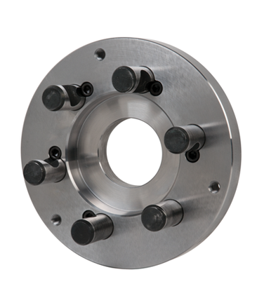
Adapter Plates
Fully Finished
- No machining required.
- Do not allow for any adjustment or compensation for the possible run-out of the spindle.
- Only fit plain back chucks with matching mounting dimensions.
Semi-Machined
- Machined on the spindle nose’s side and blank on the chuck’s side.
- Require machining to work and can be used with a wide selection of chucks.
Radially Adjustable
- Only work with the same manufacturer’s chucks.
- Do not require machining.
Lathe Chuck Jaws
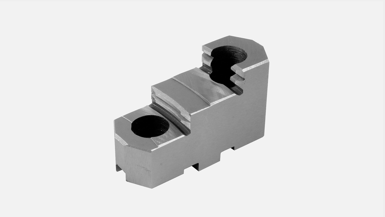
Hard Lathe Chuck Jaws
- Used for holding a workpiece on a lathe chuck.
- Made of a case-hardened steel.
- Serrated clamping surface for securing the work during a machining operation.
- Ideal for rough-finished parts.
Soft (Machinable) Lathe Chuck Jaws
- Used for holding a workpiece while turned on a lathe.
- Made of soft materials such as aluminum or mild steel.
- Can be machined to precise specifications for accurately aligning the workpiece during an operation.
- Can be cut to match the diameter of the specific part, maximizing the surface of contact.
- Ideal for use on fine-machined parts.
Lathe Chuck Jaw Designs
Solid Jaws: Maximum rigidity, slower to replace.
2-Piece Jaws: Faster changeovers; allow multiple jaw setups.
Mounting Instructions
Standard Flat Back Chucks
When using a chuck adapter plate to mount a flat back lathe chuck, proper setup is critical to ensure accuracy and safety. These instructions apply to standard flat back chucks and are not for adjustable runout models (see section below).
Steps for Mounting a Standard Flat Back Lathe Chuck:
Level the Lathe: The lathe must be leveled with a precision level to guarantee machining accuracy.
Mount the Adapter Plate or Chuck Plate: Secure the adapter plate to the spindle nose of the lathe.
Face the Adapter Plate: Take a skim cut across the full face of the adapter plate. This ensures the surface is square (90°) to the lathe spindle centerline.
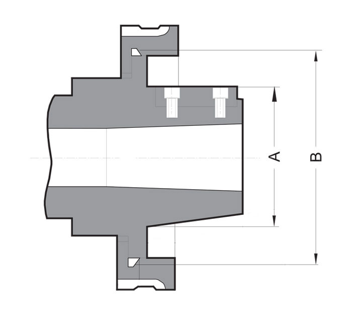
Fit the Boss and Recess: The chuck plate has a boss that must fit tightly into the recess in the back of the chuck body. The accuracy of this fit is directly related to chuck performance.
Match the Outside Diameter (O.D.): Turn the O.D. of the chuck plate to match the chuck.
Note: With 4-jaw independent chucks, the chuck body may differ in size from the plate, so adjustments are required.
Secure with Bolts: Most chucks have threaded holes in the chuck body for mounting bolts. In some cases, the plate will have threaded holes for front-insertion bolts. If necessary, transfer hole locations and drill clearance holes for proper alignment.
Adapter Plate Variations: "A" type adapters come in two versions: A-1 has two bolt circles (inner and outer), A-2 has a single bolt circle (outer) of tapped holes. The adapter is mounted to the spindle separately, and then the chuck is fastened to the plate.
Threaded Spindle Noses: For lathes with threaded spindle noses, follow the same general steps outlined above.
Adjustable Runout Chucks
Adjustable runout chucks (also marketed as “Adjust-Tru,” “Set-Tru,” “Zero-Set,” “Set-Rite,” “Hi-Tru,” “Accu-Chuck”) allow fine-tuning of runout for maximum accuracy.
Mounting Procedure for Adjustable Runout Chucks:
Use the Matching Adapter: Each brand requires its own matching adapter. Adapters are not interchangeable unless explicitly specified by the manufacturer.
Initial Setup: A ground pin is clamped securely in the chuck. A test indicator is used to measure runout while adjusting screws are tightened to align the chuck.
Adapter Plate Design: The design permits adjusting screws to contact an extended boss on the plate, allowing precise movement of the chuck body.
Zeroing the Adapter Plate: Before final mounting, take a skim facing cut across the flange to ensure squareness. Compare all dimensions to the back of the specific chuck and machine as necessary.
Final Lock-In: Once the chuck is zeroed in and aligned, lock it into position using the adjusting screws. Verify accuracy again with the ground pin and test indicator.
To request a quote, please login to your existing account or register a new one. This helps us provide you with a personalized experience and keep track of your requests.