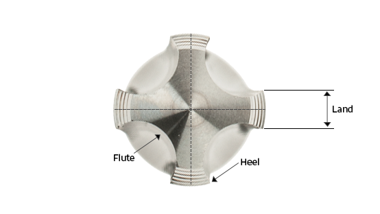
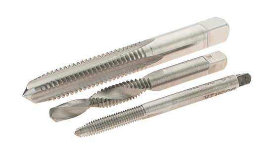
Different types of taps are used to cut threads into pre-drilled or punched holes, allowing screws or bolts to hold materials together. The cutting edges at the front of the tap remove material from the workpiece, producing chips that are pushed ahead, drawn up through the flutes, or collected within them. These flutes also help clear chips and cutting fluids from the hole.
Types of Taps: A Practical Guide for Threading Tasks
Get the facts on common tap types, class of fit, thread limits, finishes, and more, all in one place.
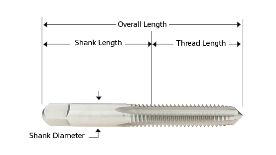
DIAGRAM OF A TAP
Essential Tips:
Taps feature multiple flutes, which are grooves or valleys cut into the body of the tap, that allow chips to escape during threading. A higher number of flutes increases tap strength but reduces space or chip flow.
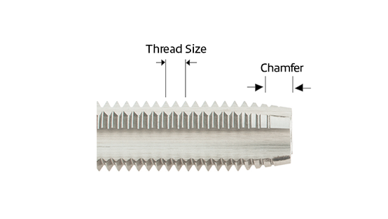
Thread size refers to the number of threads per inch (TPI) in imperial measurements and is measured along the length of the tap. Thread pitch refers to metric sizes.
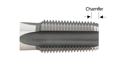
The chamfer is the tapered section at the tip of the tap. Both the chamfered portion of the tap and the first full thread beyond the chamfer help form the final thread in the workpiece.
Types of Taps & Their Applications:
Acme Tap
Acme taps create trapezoidal threads with a 29° thread angle, designed for rotary and linear motion in machinery. They're commonly used to manufacture components like valves, jacks, and other mechanisms built to move heavy loads.

Combination Drill & Tap
Combination drill & taps create holes and cut threads in a single pass at high speeds. These self-centering tools are ideal for through holes up to twice the depth of the tap diameter. Common applications include construction, maintenance and repair, and general assembly work.

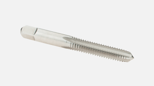
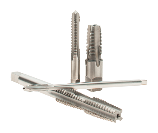
Straight Flute Tap
Straight flute taps cut threads in blinds or through holes. They are suitable for both hand-tapping and general-purpose machine operations.
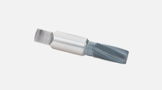
Pipe Tap
Pipe taps cut internal threads into parts or fittings that will mate with threaded pipe or fittings to make a pressure-tight joint. Pipe threads require higher cutting forces than regular machine thread tapping because the threads require 100% thread depth. All threads on tapered pipe taps are cutting. For more information, please see our Pipe Taps Guide.
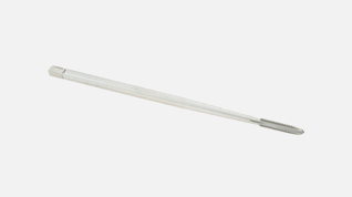
Extension Tap
Extension taps are designed with an extended shank to reach deep holes or areas with limited access. They feature standard thread profiles and are ideal for applications that require extra reach during tapping.
Nut Tap
Nut taps are designed for cutting internal threads in nuts and other small holes. They feature long threads and extended shanks for reaching hard-to-reach holes.
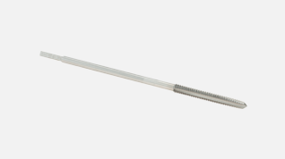
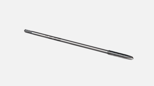
Pulley Tap
Pulley taps are used for tapping hard-to-reach areas, pulleys, and set screw holes. They feature the same basic thread dimensions as hand taps but have longer shanks to provide extended reach. Pulley taps are also suitable for general-purpose applications where access is limited.
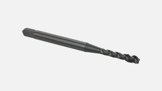
Spiral Flute Tap
Spiral flute taps are ideal for threading blind holes in materials like aluminum, brass, and softer steels. Their spiral flute design pulls chips up and out of the hole, which helps prevent clogs and ensures smoother chip evacuation.
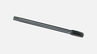
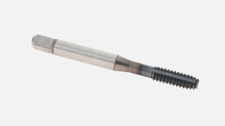
Spiral Point Tap
Spiral point taps are used for tapping through holes. They have a flute geometry that shoots chips ahead of the cutting action to reduce loading and clogging within the flute.
Thread Forming Tap
Thread forming taps create threads by displacing material rather than cutting it, producing no chips in the process. They are ideal for use on mild steels, carbon steels, and low to medium alloys. For more details, read our Thread Forming Taps Buying Guide.
Screw Thread Inserts (STI) Tap
Screw Thread Inserts (STI) taps cut oversized threads in through holes for screw thread inserts. For more information, please see Screw Thread Inserts (STI) Buying Guide.
Class of Fits & Thread Limits (H&D):
Class of Fit is the standard identification system that describes the tolerance and closeness of fit between the tap and threaded hole. Unified threads are designated as A (external) or B (internal), while metric threads use H for internal and G for external classifications.
Example Applications:
Class 1A & 1B - For frequent, quick, loose assembly.
Class 2A & 2B - Fit is medium loose to eliminate seizure in assembly. For use with screws, bolts, and nuts.
Class 3A & 3B – Requires accuracy of thread. The use of gages ensures a tight fit.
Thread Limit is a standard notation system that indicates a level of tolerance for the thread outside the basic thread size of the tap. In this system, "H" is used for inch sizes and "D" for metric sizes, each followed by a number. Thread limits help users select the appropriate tap size to achieve the desired Class of Fit. The difference in size from one H limit to the next is 0.0005″ increments for taps through 1″ diameter. Sizes over 1″ diameter are separated by .001″ diameter increments. If the threads in the part are too loose, smaller numbers such as H1 or H2 are used. If the threads are too tight, the H limit number is increased. Choosing the correct H limit helps ensure the threads meet the tolerance requirements of the part print. A good rule of thumb: always select the largest H limit that still meets the class of fit; this maximizes tool life and threading efficiency.
Thread Limit (H&D) Cross Reference Guide
H1/D1 | Basic plus .0005" - .0010" |
H2/D2 | Basic plus .0005" - .0010" |
H3/D3 | Basic plus .0010" - .0015" |
H4/D4 | Basic plus .0015" - .0020" |
H5/D5 | Basic plus .0020" - .0025" |
H6/D6 | Basic plus .0025" - .0030" |
H7/D7 | Basic plus .0030" - .0035" |
H8/D8 | Basic plus .0035" - .0040" |
H9/D9 | Basic plus .0040" - .0045" |
H10/D10 | Basic plus .0045" - .0050" |
H11/D11 | Basic plus .0050" - .0055" |
H12/D12 | Basic plus .0055" - .0060" |
Chamfer Styles:
Chamfer refers to the length of the tapering threads at the front of the tap. Both the chamfered portion of the tap and the first full thread beyond the chamfer produce the finished thread of the part.
Bottoming Chamfer
Used for threading blind holes close to the bottom. These taps have 1 to 2 chamfered threads.
Modified Bottoming Chamfer
Similar to bottoming chamfers, but are slightly longer and have more teeth and 2 to 2.5 chamfered threads. Ideal for threading near the bottom of blind holes.
Plug Chamfer
The most commonly used type of tap. Plug chamfers have 3 to 5 chamfered threads and are effective for both blind holes and through holes.
Semi-Bottoming Chamfer
Designed for threading blind holes with a balance between thread engagement and chip clearance. These have 3 to 3.5 chamfered threads.
Taper Chamfer
Also known as starter taps, taper chamfers feature a longer lead with 7 to 10 chamfered threads and require less cutting force.
Spiral Point Plug Chamfer
Used in general-purpose applications, spiral point plug taps have 4 to 5 chamfered threads.
Standard Finishes:
Bright provides a smooth, polished finish that increases chip flow in softer materials like aluminum, wood, and plastic.
Titanium Nitride (TiN) is a multi-purpose coating that increases chip flow in softer materials. Its heat and wear resistance allows tools to run at higher speeds than uncoated tools.
Titanium Carbonitride (TiCN) is harder and more wear-resistant than TiN. TiCN is ideal for stainless steel, cast iron, and aluminum alloys.
Oxide, also known as black oxide or steam oxide, is a surface treatment that reduces chip buildup, galling, and welding. Commonly used on low-carbon steel, stainless steel, and other ferrous metals.
Chrome Plate is a bright electroplated coating that offers excellent anti-friction properties. It is commonly used on steel, aluminum, brass, copper, or other non-chromium metals.
Nitride is a thin, hard-shell coating that supports the surface hardness of the tool. Best for applications involving abrasive or high-wear conditions.
Aluminum Chromium Nitride (AlCrN) offers higher heat resistance than AlTiN. Ideal for machining aerospace materials, nickel alloys, stainless steel, titanium, cast iron, and carbon steel.
Aluminum Chromium Titanium Nitride (AlCrTiN) is a high heat and wear-resistant multilayered PVD coating. AlCrTiN is engineered to extend tool life and deliver a superior thread finish in demanding applications.
TiCN PLUS (Titanium Carbonitride + Titanium Nitride) is an all-purpose finish designed to increase tool life by 2–4 times compared to standard TiN coatings. The heat and hardness resistance allows the tool to run at higher speeds than uncoated tools.
Uncoated tools do not feature supportive treatments on the cutting edge. Best suited for general-purpose applications on nonferrous metals at reduced speeds.
Standard Materials:
Cobalt is harder than high-speed steel and provides better wear resistance. It is ideal for use on high-tensile alloys.
High-Speed Steel (HSS) offers good wear resistance and is suitable for general-purpose applications on both ferrous and nonferrous materials.
Solid Carbide provides greater rigidity than high-speed steel. It offers excellent heat resistance and is best suited for high-speed applications on cast iron, nonferrous materials, plastics, and other hard-to-machine materials.
Vanadium High-Speed Steel (HSSE) is a blend of high-speed steel, carbon, vanadium carbide, and other alloys that improve abrasive wear resistance and toughness. It is commonly used for general-purpose machining of stainless steels and high-silicon aluminum.
Powdered Metal (PM) is tougher and more cost-effective than solid carbide. It is ideal for highly abrasive materials, including high-silicon aluminum.

Calculations:
Calculating Tap Drill Sizes
For Cutting Taps:
Tap Drill Size = Tap Basic Major Diameter - Pitch
Drill Size = Major Diameter - [(.01299 x desired % of thread) ÷ Threads per Inch]
Drill Size (mm) = Major Diameter - (desired % of thread x pitch (mm) ÷ 76.98)
For Forming Taps:
Tap Drill Size = Major Diameter - (Pitch ÷ 2)
Drill Size = Major Diameter - [(0.0068 x desired % of thread) ÷ Threads per Inch]
Drill Size (mm) = Major Diameter - (desired % of thread x pitch (mm) ÷ 147.06)
Formulas produce threads depending on the workpiece material. Verify findings with a ″Machinery Handbook″, MSC Order No. 85605756.
Calculating the Percentage of Thread
The percentage of Thread is calculated by taking half the difference between the major and minor diameters of an internal thread, then dividing that value by the thread height. The formula is:
% of Full Thread = (Threads per Inch × (Major Diameter – Drill Diameter)) ÷ 0.01299
How to Read a Tap Size
Example: 1/4 - 20NC
The 1/4 represents the diameter of the thread in inches. The 20 represents the number of threads per inch or TPI. Standard taps are either standard coarse series threads NC (1/4-20), fine series threads NF (1/4-28), or extra fine series NEF (1/4-32). There are other standard tap designations, such as NPT or NPTF for tapered pipe threads. Special taps are usually designated NS, indicating a special thread size.
Inch - Tap & Drill Chart 75% Thread
Thread Size | Drill Size | Thread Size | Drill Size | Thread Size | Drill Size | Thread Size | Drill Size |
|---|---|---|---|---|---|---|---|
0-80 | 3/64 | 5-44 | 5-44 | 1/4-28 | 3 | 9/16-18 | 33-64 |
1-64 | 53 | 6-32 | 36 | 5/16-18 | F | 5/8-11 | 17-32 |
1-72 | 53 | 6-40 | 33 | 5/16-24 | I | 5/8-18 | 37-64 |
2-56 | 50 | 8-32 | 29 | 3/8-16 | 5/16 | 3/4-16 | 21-32 |
2-64 | 50 | 8-36 | 29 | 3/8-24 | Q | 3/4-10 | 11-16 |
3-48 | 47 | 10-24 | 25 | 7/16-14 | U | 7/8-9 | 49/64 |
3-56 | 46 | 10-32 | 21 | 7/16-20 | W | 7/8-14 | 13/16 |
4-40 | 43 | 12-24 | 17 | 1/2-13 | 27/64 | 1-8 | 7/8 |
4-48 | 42 | 12-28 | 15 | 1/2-20 | 29/64 | 1-12 | 59-64 |
5-40 | 39 | 1/4-20 | 7 | 9/16-12 | 31/64 | 1-14 | 15-16 |
Metric - Tap & Drill Size 70-75%
Thread Size | Drill Size | Thread Size | Drill Size | Thread Size | Drill Size |
|---|---|---|---|---|---|
M1.6 x .35 | 1.25 | M4.5 x .75 | 3.75 | M12 x 1.75 | Y |
M2 x 0.4 | 1.6 | M5 x .8 | 4.2 | M14 x 2 | 12 |
M2.5 x .45 | 2.05 | M6 x 1 | 5 | M16 x 2 | 14 |
M3 x .5 | 2.5 | M7 x 1 | 6 | M18 x 2.5 | 15.5 |
M3 x .6 | 2.9 | M8 x 1.25 | 6.75 | M20 x 2.5 | 17.5 |
M4 x .7 | 3.3 | M10 x 1.5 | 8.5 | - | - |
Inch - Tap Thread Length
Thread Size | Thread Length | Thread Size | Thread Length | Thread Size | Thread Length | Thread Size | Thread Length |
|---|---|---|---|---|---|---|---|
0 | 5/16 | 8 | 3/4 | 1/2 | 1-21/32 | 1-1/8 | 2-9/16 |
1 | 3/8 | 10 | 7/8 | 9/16 | 1-21/32 | 1-1/4 | 2-9/16 |
2 | 7/16 | !2 | 15/16 | 5/8 | 1-13/16 | 1-3/8 | 3 |
3 | 1/2 | 1/4 | 1 | 11/16 | 1-13/16 | 1-1/2 | 3 |
4 | 9/16 | 5/16 | 1-1/8 | 3/4 | 2 | - | - |
5 | 5/8 | 3/8 | 1-1/4 | 7/8 | 27/32 | - | - |
6 | 11/16 | 7/8 | 1-7/16 | 1 | 21/2 | - | - |
Metric - Tap Thread Length
Thread Size | Thread Length | Thread Size | Thread Length | Thread Size | Thread Length |
|---|---|---|---|---|---|
M1.6 x .35 | 5/16 | M5 x .8 | 7/8 | M16 x 2 | 1-13/16 |
M2 x 0.4 | 7/16 | M6x1 | 1 | M18 x 2.5 | 1-13/16 |
M2.5 x .45 | 1/2 | M7 x 1 | 1-1/8 | M20 x 2.5 | 2 |
M3 x .5 | 5/8 | M8 x 1.25 | 1-1/8 | M24 x 3 | 2-7/32 |
M3 x .6 | 1-1/16 | M10 x 1.5 | 1-1/4 | M30 x 3.5 | 2-9/16 |
M4 x .7 | 3/4 | M12 x 1.75 | 1-21/32 | M36 x 4 | 3 |
M4.5 x .75 | 7/8 | M14 x 1 | 1-21/32 | - | - |
Terminology:
American National Standards Institute (ANSI): Sets industry standards and product guidelines to ensure conformity and maintain the highest product standards.
Body: Made up of the flutes, land, core, diameter, thread length, and chamfer. These elements produce the threaded hole.
Base of the Thread: The bottom section of the thread.
Blind Hole: A hole that does not go all the way through the part. The threads must come as close as possible to the bottom of the drilled hole.
Coolant Fed/Thru Coolant: Fluid that helps prevent chip accumulation in blind holes, reducing the risk of tap breakage.
Core: The center portion of the tap that separates the flutes and provides structural strength. As the number of flutes increases, the core becomes larger, increasing the tap’s strength.
Crest: The top surface joining two sides of a thread. In an internal thread, the crest is at the minor diameter; in an external thread, it is at the major diameter.
Deutsche Industrie Norm (DIN): German standards organization responsible for setting industrial product standards.
Diameter: The thread diameter of a tap is largest at the front, behind the chamfer. It decreases slightly toward the shank, a feature called back taper, which creates clearance between the tap and the workpiece.
Ground Thread: Provides more accurate threads than cut taps and is held to tighter limits and tolerances.
Length of Engagement: The length of contact between two mating threaded parts.
Major Diameter: The largest diameter of the thread; also known as the outside diameter.
Minor Diameter: The smallest diameter of the thread; also known as the root diameter.
Pitch: The distance between a point on one thread and the corresponding point on the next. Pitch is equal to 1 divided by the number of threads per inch.
Square (Flats): The square end of the tap shank.
Square Length: The length of the square portion.
Size of Square: The thickness of the square portion.
Shank: The part of the tap that fits into the tap holder. The end is squared for driving and rotating the tap. The square surface is known as the flats.
Thread Height: The radial distance between the crest and the base of the thread.
Through Hole: A hole that goes all the way through the part.
To request a quote, please login to your existing account or register a new one. This helps us provide you with a personalized experience and keep track of your requests.