Tap testing measures the vibration of mechanical structures to assess their response to forces. MSC’s Dr. Tony Schmitz describes the hardware and processes needed for this diagnostic test.
Tap testing measures the vibration response of the tool, holder and spindle combination so that stable machining parameters can be selected without trial and error.
The test requires hardware including a force input mechanism, a vibration measurement device and a signal analyzer.
Force excitation can be applied by fixed-frequency sine wave, random signal and impulse.
Force input can be achieved by shaker (magnetic or hydraulic) or impact hammer.
What Is Tap Testing and How Does It Work?
Tap testing is a diagnostic method used to assess the vibration performance of mechanical structures, such as machine tool spindles, by measuring their response to a controlled impact. The resulting data can help select stable machining parameters.
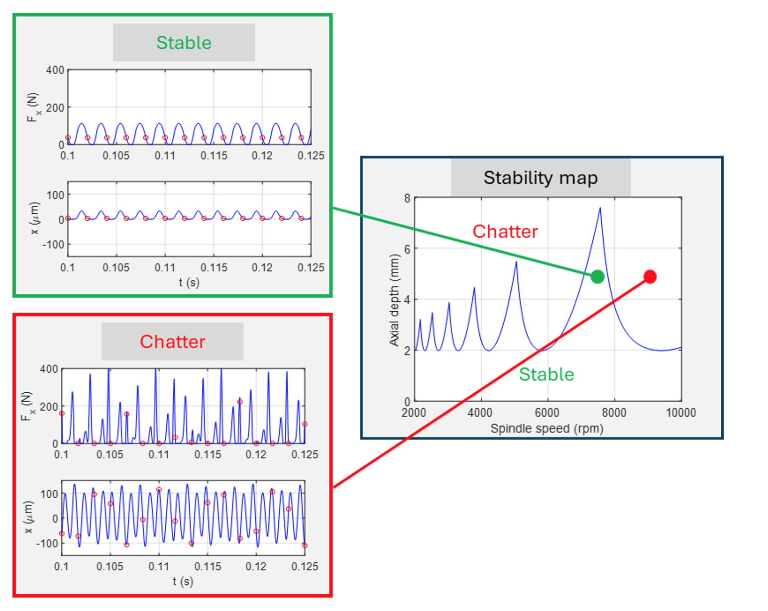
In tap testing, we use an instrumented hammer to excite a structure and measure the vibration response with a transducer, such as an accelerometer. The purpose of this test is to identify the frequency response function (FRF) for the selected mechanical structure. Given the FRF, we can calculate a stability map, which separates combinations of spindle speed and axial depth that produce chatter (i.e., above the blue boundary) from those that do not (below the boundary) [1]. This enables the selection of stable machining parameters without trial and error; see Fig. 1.
Read more: MSC MillMax takes the guesswork out of optimizing milling applications with a scientifically proven method that delivers proven results.
Figure 1: Milling stability map.
The basic hardware required to measure FRFs is:
A mechanism for known force input across the desired frequency range (or bandwidth).
A transducer for vibration measurement, again with the required bandwidth.
A dynamic signal analyzer to record the time-domain force and vibration inputs and convert these into the desired FRF.
Common Types of Force Excitation
There are three common types of force excitation:
Fixed-Frequency Sine Wave
The FRF is determined one frequency at a time. At each frequency within the desired bandwidth, the sinusoidal force is applied, the response to the force input is averaged over a short time interval, and the FRF is calculated. This is referred to as a sine sweep test.
Random Signal
The frequency content of the random signal may be broadband (white noise) or truncated to a limited range (pink noise). The average is applied over a fixed period, but all the frequencies within the selected bandwidth are excited in a single test.
Impulse
A short-duration impact is used to excite the structure, and the corresponding response is measured. This approach enables a broad range of frequencies to be excited in a single, short test. Multiple tests are typically averaged in the frequency domain to improve coherence, or the correlation between the force and vibration signals.
Common Types of Force Input Hardware
To generate any of three types of excitation forces, two common types of force input hardware are applied:
Shaker
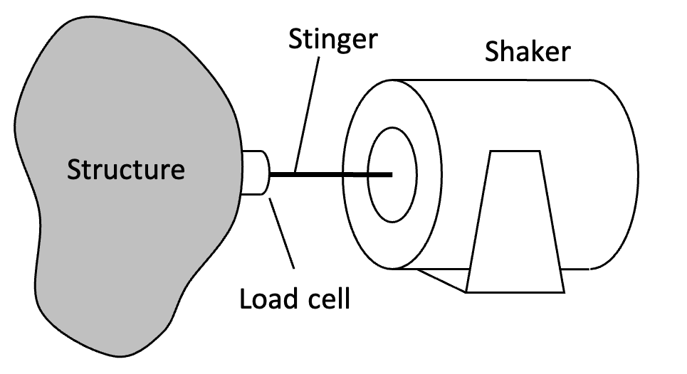
These systems include a harmonically driven armature and a base. The armature may be actuated along its axis by a magnetic coil or hydraulic force. The magnetic coil, or electrodynamic, configurations can provide excitation frequencies of tens of kilohertz with force levels from tens to thousands of newtons (increased force typically means a lower frequency range). Hydraulic shakers offer high force with the potential for a static preload (i.e., the average, or mean, force is not zero) but relatively lower frequency ranges. In either case, the force is often applied to the structure of interest through a stinger, or a slender rod that supports axial tension and compression but not bending or shear. This ensures that the force is applied in a single direction only. A load cell is incorporated in the setup to measure the input force; see Fig. 2.
Impact Hammer
An impact hammer incorporates a force transducer located at a metal, plastic or rubber tip to measure the force input during a hammer strike. When a hammer is used in conjunction with a vibration transducer, the measurement procedure is referred to as tap testing. The energy input to the structure is a function of the hammer mass; a larger mass provides more energy. Therefore, many sizes are available. Also, the excitation bandwidth of the force input depends on the mass and tip stiffness. Stiffer tips tend to excite a wider frequency range but also spread the input energy over this wider range. Softer tips concentrate the energy over a lower frequency range. Hard plastic and metal tips provide higher stiffness, while rubber tips give reduced stiffness.
Figure 2: Shaker setup.
Common Types of Vibration Transducers
Vibration transducers are available in both noncontact and contact types. While noncontact transducers, such as capacitance probes and laser vibrometers, are preferred because they do not affect the structure dynamics, contacting types, such as accelerometers, are often more convenient to implement. As a compromise, low-mass accelerometers may be used to minimize the influence on the test structure. They are attached at the location of interest using wax, adhesive, a magnet or a threaded stud and then removed when the testing is completed.
Analyzing the Dynamic Signal
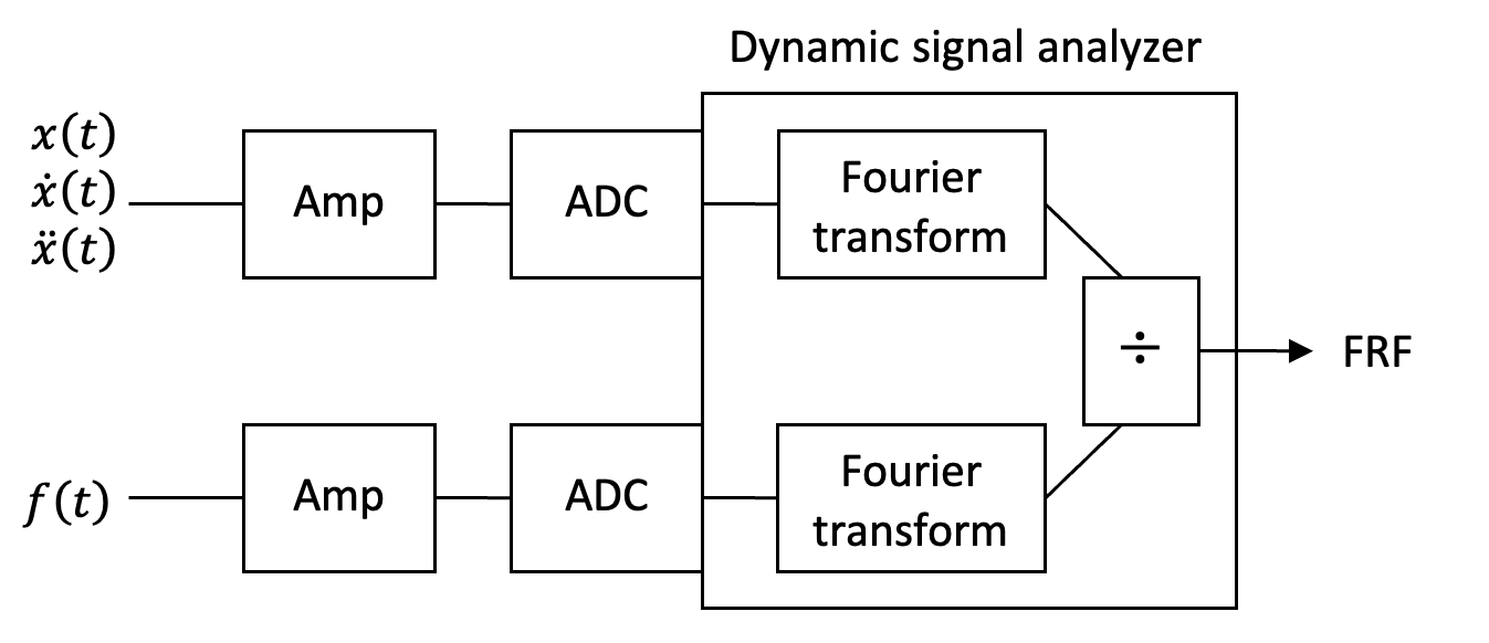
A dynamic signal analyzer includes input channels for the time-domain force and vibration signals and computes the Fourier transform (mathematical method) of these signals to convert them to the frequency domain. It then calculates the ratio of the frequency-domain vibration signal to the frequency-domain force signal; this ratio is the FRF. A schematic of the setup is provided in Fig. 3. It includes the time-domain force and vibration (which may take the form of displacement [x], velocity [ẋ] or acceleration [ẍ]) inputs and amplifiers for each. The amplifiers are used to increase the magnitude of the signals. The force and vibration are analog signals, which are continuous in time. However, recording these signals with the analyzer requires sampling them at small time intervals or digitizing them. This process is completed using an analog-to-digital converter (ADC). These digital signals are then used in the FRF calculation by the dynamic signal analyzer.
Based on the vibration input type, the FRF may be expressed as:
Receptance or compliance – the ratio of displacement to force.
Mobility – the ratio of velocity to force.
Accelerance or inertance – the ratio of acceleration to force.
Figure 3: Schematic of FRF measurement setup.
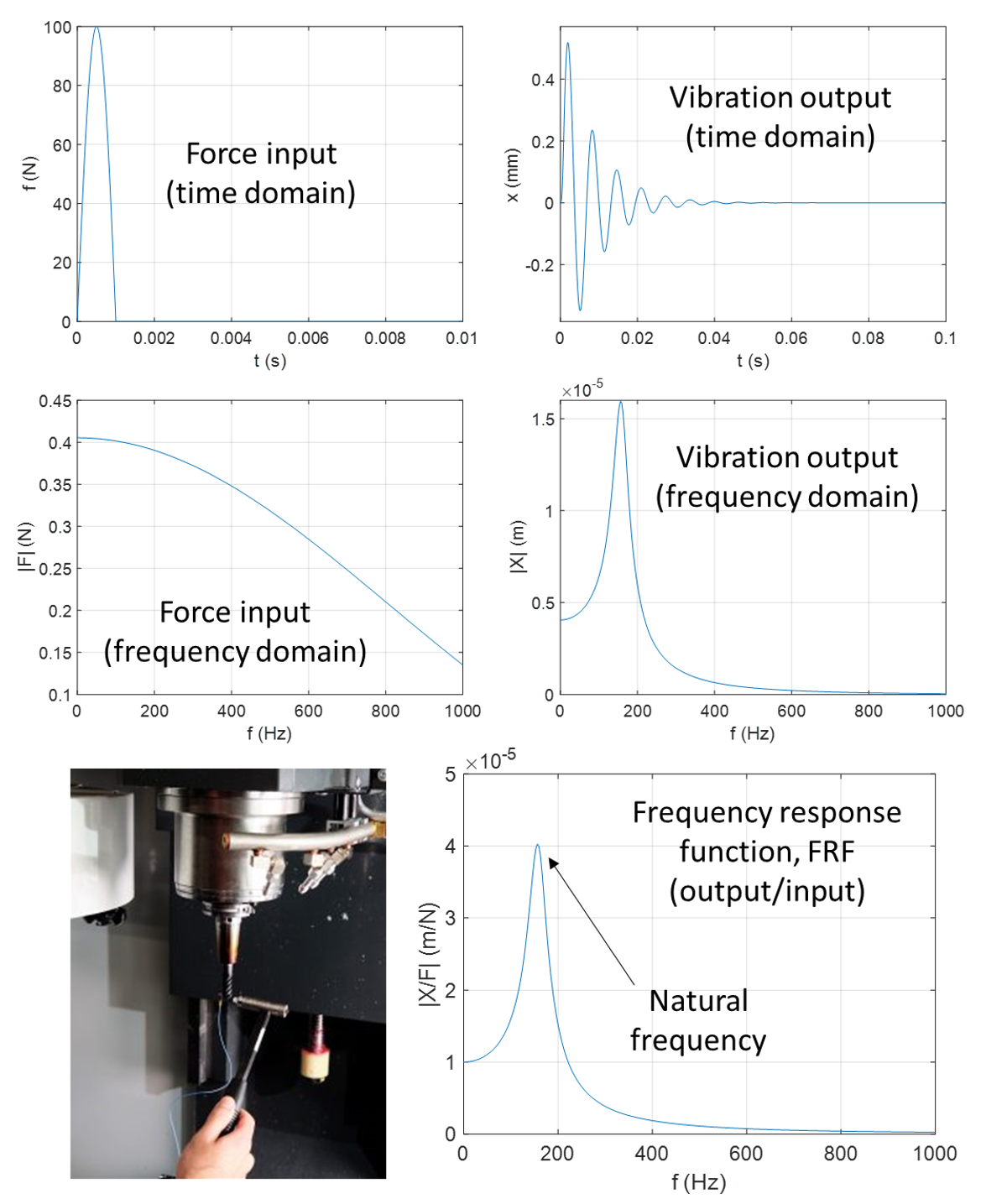
Figure 4: Key elements of the tap test.
Key Elements of the Tap Test
Fig. 4 identifies key elements of the tap test. The lower-left photograph shows a hammer being used to tap a tool tip and an accelerometer (attached with wax to the tool tip) being used to measure the vibration response. The top row displays the time responses for the force and vibration. We see that the tap produces a short-duration force input. Due to this force, the tool vibrates with a decaying amplitude (due to damping). The middle row shows the conversion of these signals to the frequency domain. The tap excites a wide range of frequencies. The bottom row displays the FRF. From this plot, we can identify the natural frequency, stiffness and damping ratio for each vibration mode.
References
Schmitz, T. and Smith, K.S., 2019. Machining Dynamics: Frequency Response to Improved Productivity, Second Edition. Springer.
Dr. Tony Schmitz is a distinguished technical fellow at MSC who offers a rare blend of deep academic rigor and real-world manufacturing insight. He has a Ph.D. in mechanical engineering and more than 25 years of experience in machining dynamics, vibration, metrology and advanced manufacturing. He has authored more than 200 peer-reviewed papers as well as three engineering textbooks, and he holds 12 U.S. patents.
To request a quote, please login to your existing account or register a new one. This helps us provide you with a personalized experience and keep track of your requests.