



The R8 taper is commonly used in manual milling machines, especially Bridgeport-style mills. Technically, it's not a true taper by Machinery’s Handbook standards. Instead, it features a 3-1/16" long undercut straight shank that is secured using a 7/16"-20 threaded drawbar.
Tool Holders: Precision Starts at the Spindle
From R8 to HSK, the right tool holder ensures performance in every cut. Learn how to choose tool holders for milling, CNC, and high-speed operations.
What Is a Tool Holder?
A tool holder is the connection point between a precision cutting tool and a machine’s spindle. It plays a critical role by securely holding the tool in place during operation. A standard tool holder includes three base elements:
A taper connection
A retention mechanism
A cutting tool interface
Overall, tool holders are essential in CNC machining, milling, drilling, and high-speed operations, where accuracy, rigidity, and balance are vital.
Types of Tapers
The tool holder you choose must match the taper design of your machine spindle. Tapers are not interchangeable, so understanding taper types is crucial for efficient operation.
Manual Tapers
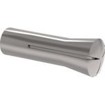
R8 Taper
The taper portion consists of a 15/16" long cone section with a 16.85° included angle, which provides alignment and engagement.
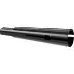
Morse Taper
Available in eight sizes identified by the abbreviation MT and a digit. For example, a Morse Taper number 4 would be MT4. The MT2 taper is commonly used in drill presses up to ½″ capacity. Morse tapers can have three types of ends:
- Tang: allows removal with a drift
- Threaded: secured by a drawbar
- Flat: without tang or threads
CNC TAPERS
Tool Holder Selection for Higher Speeds
When choosing a tool holder for high-speed applications, focus on:
Types of Tool Holders
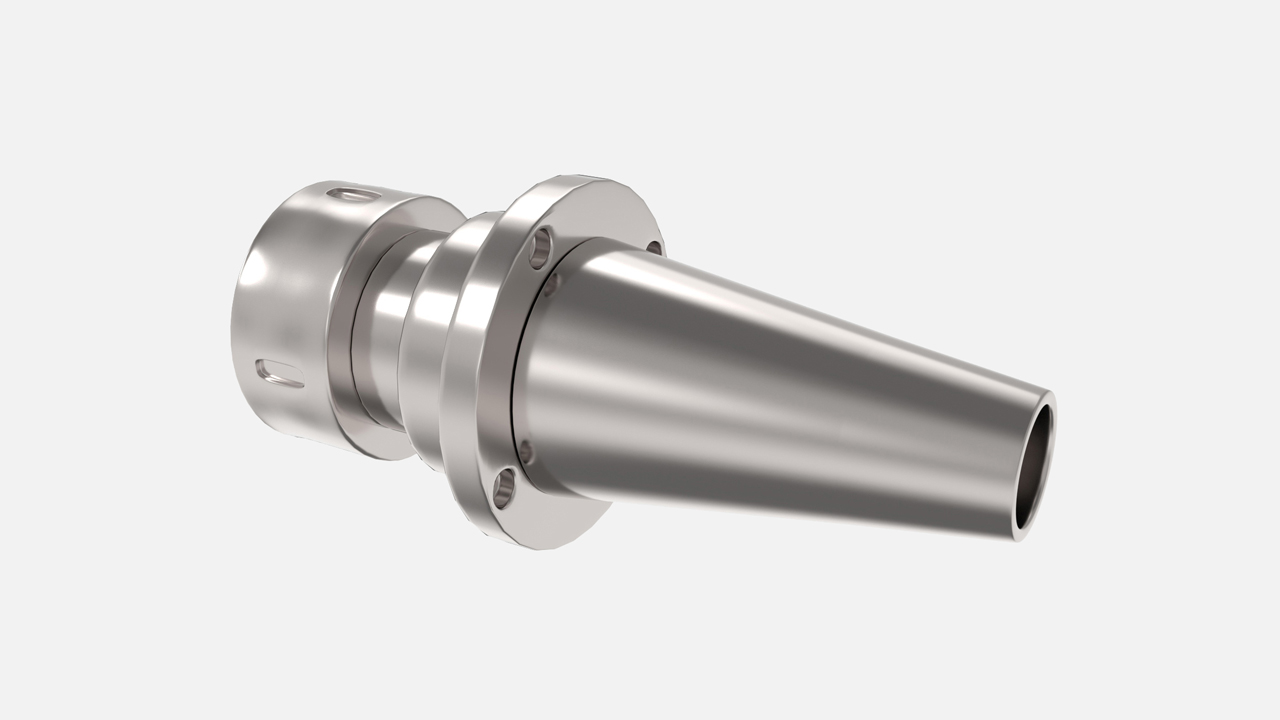
Collet Chuck
A collet chuck includes a chuck body, shank, and fastening unit. They are very versatile since different collet sizes can be used in one holder, allowing for different-sized tools to be held. They come in a variety of shank sizes and types.
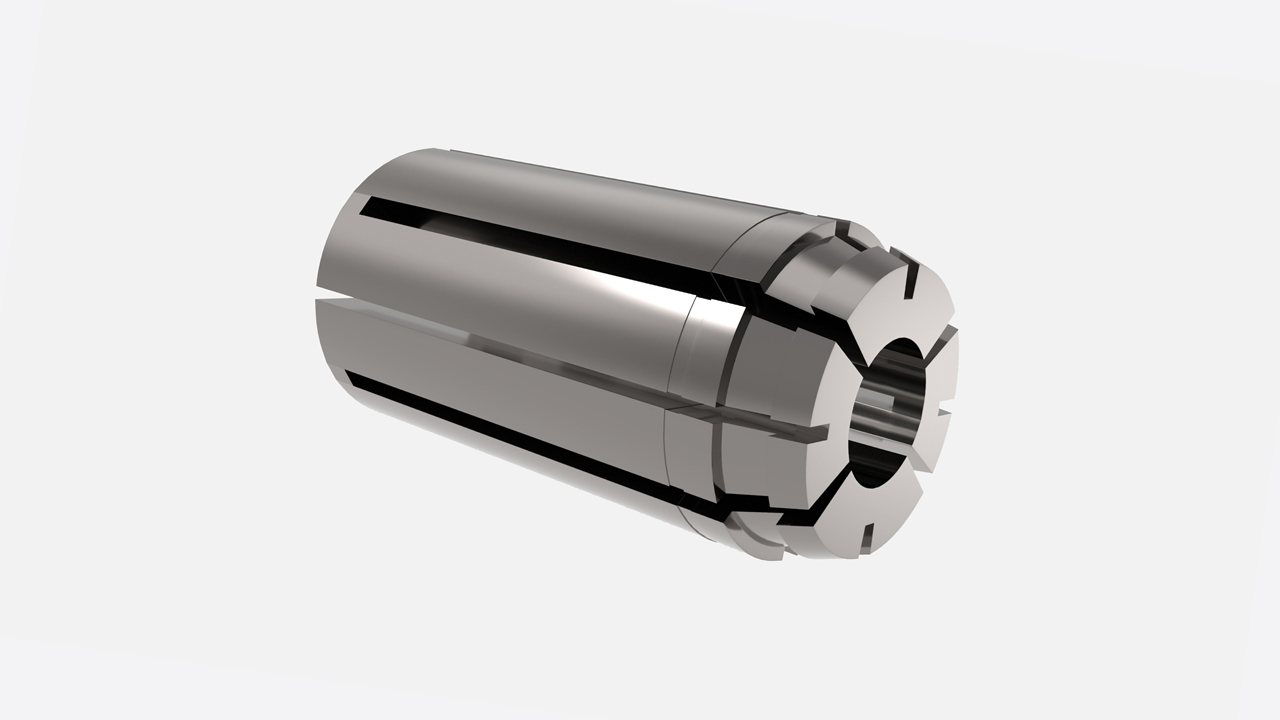
Single Angle Collet System
1. ER Collet Chuck: Ideal for most drilling and lighter, higher-speed milling applications. ER collets offer very good concentricity and balance. Safe operational speed as high as 30,000 rpm. Larger sizes have a limit based on centrifugal forces.
2. TG/PG Series: Ideal for heavy drilling and some milling applications. The system provides good concentricity and good grip force. The nut system does not lend itself to good balance considerations at higher speeds.
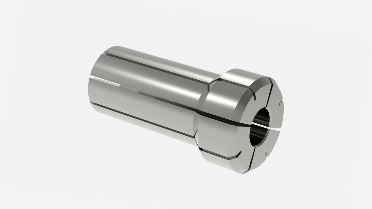
Double Angle Collet System (DA Series)
DA collets are best for smaller drilling applications where clearance is necessary. This system is the simplest to use but lacks the characteristics of concentricity and grip force. Not suitable for precision high-speed applications.
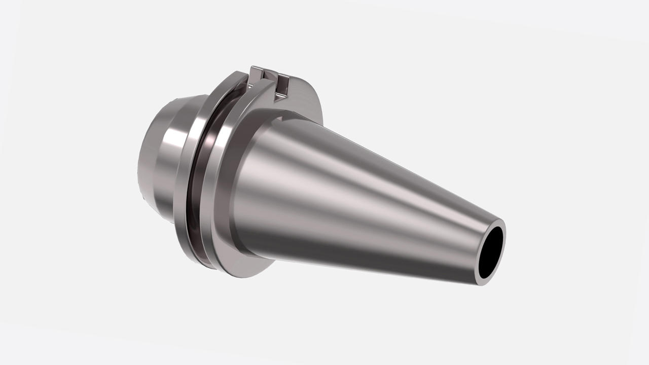
End Mill Holders
End mill holders are commonly used for milling applications requiring strong clamping. They offer more rigidity than collets and are available in Weldon type for using tools with Weldon flats.
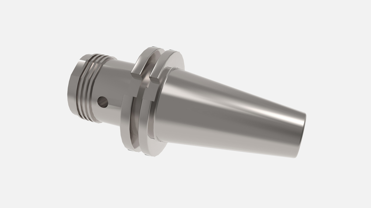
Hydraulic Toolholders
Hydraulic toolholders are user-friendly and ideal for close-tolerance operations where precision and tool life are critical, especially when using high-value round tools. They minimize tool chatter with vibration damping and offer excellent balance characteristics, while delivering high runout accuracy.
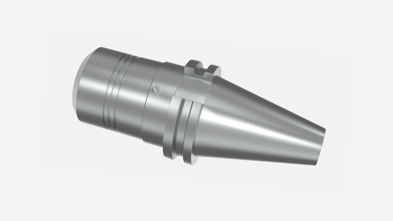
Milling Chucks
Ideal for precision in moderate and lower speed milling and nominal drilling applications. Milling chucks offer very good concentricity and good sideload capability. A movable, large clamping nut restricts the balance and centrifugal force capability, limiting the speed to 8,000 to 12,000 rpm.
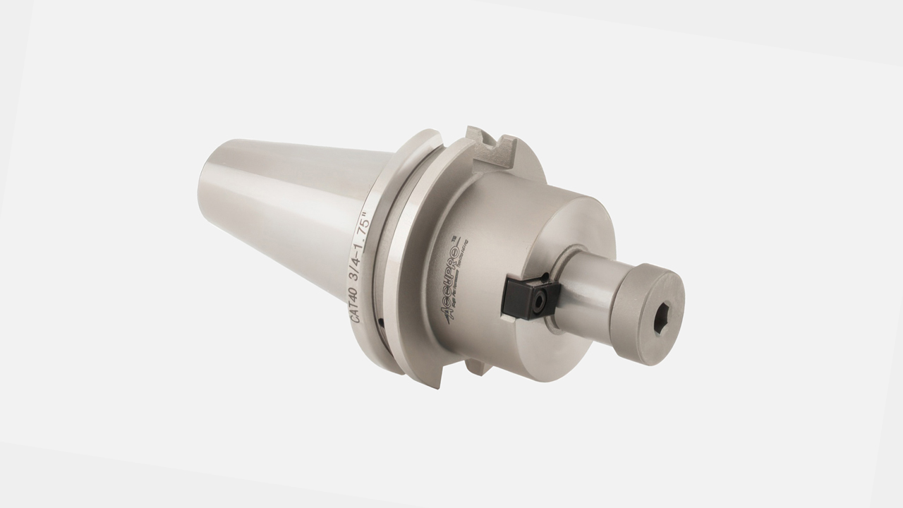
Shell Mill Holders
Shell mill holders are designed to secure milling cutters that use the American National Standard (ANS) mount for shell mills. These tool holders are commonly used with indexable cutters for face milling, contouring, and other high-load applications.
Depending on the cutter manufacturer's specifications, shell mill tool holders may use a lock screw, socket head cap screws, or both to secure the cutter in place. The correct hardware is typically included with the holder and varies by tool size.
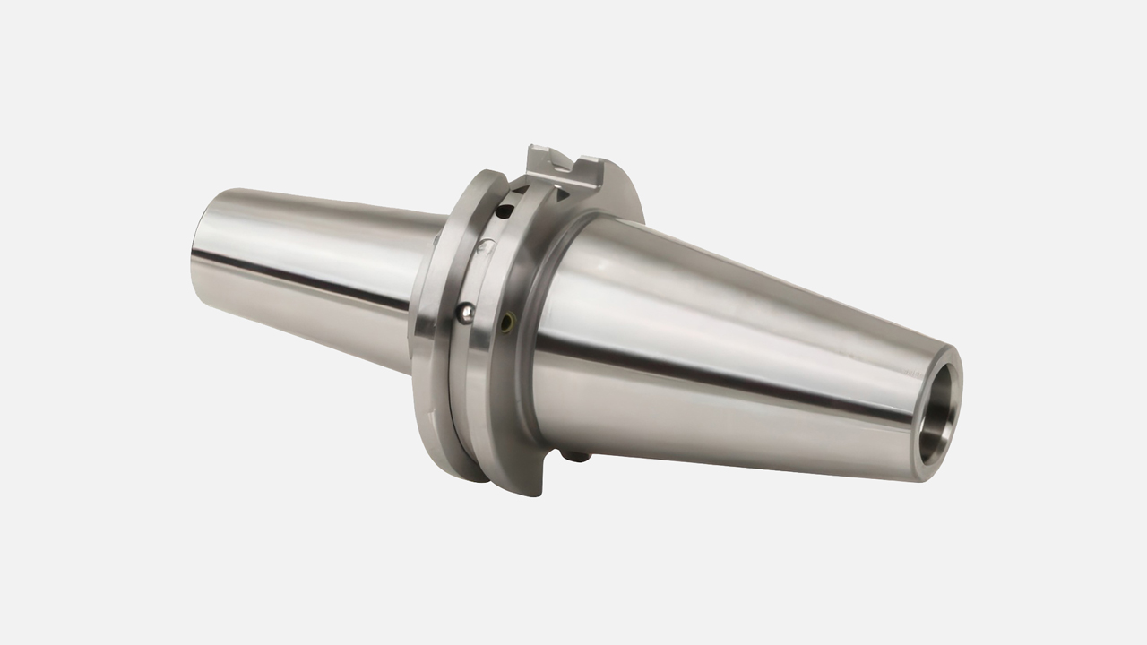
Shrink Fit Holders (Heat Shrink)
Shrink fit holders, also known as heat shrink tool holders, are ideal for high-speed and high-feed milling or nominal-size drilling. These holders offer exceptional concentricity and balance, making them well-suited for precision applications.
Shrink fit holders feature no moving parts and a thin nose profile, allowing for excellent rigidity and clearance in tight spaces. Their design minimizes the effects of centrifugal force, enabling safe operating speeds at extremely high RPMs.
To use shrink-fit tool holders effectively, a heat-shrink machine is required to achieve optimal performance.
To request a quote, please login to your existing account or register a new one. This helps us provide you with a personalized experience and keep track of your requests.