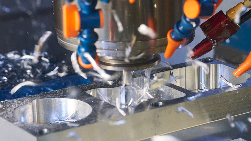
Successful chip control
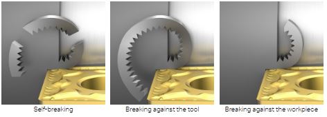
Chip control is one of the key factors in turning and there are three principle chip breaking alternatives:
Self-breaking (for example gray cast iron)
Breaking against the tool
Breaking against the workpiece
Factors that influences chip breaking
Insert geometry: Based on the width of chip room and the design of micro- and macro-geometry, the chip can be opened or more compressed
Nose radius: Smaller nose radius controls the chip more than a bigger nose radius
Entering (lead) angle: Depending on angle, the chip is directed in different ways: toward shoulder or out from shoulder
Cutting depth: Depending on the workpiece material, a larger cutting depth will influence the chip breaking, leading to bigger forces to break and remove the chip
Feed: A higher feed will generally create stronger chips. In some cases, it can help chip breaking and chip control
Cutting speed: Change of cutting speed can influence the chip breaking performance
Material: A short-chipping material (for example cast iron) is generally easy to machine. For materials with excellent mechanical strength and resistance to creep
(the tendency for solids to slowly move or deform under stress, for example, Inconel), chip breaking is of greater concern
Cutting data for turning
Always consider the machine, tool, insert and material when choosing the correct speeds and feeds for turning.
Start at a low feed rate to ensure insert security and surface finish, then increase the feed rate to improve chip breaking
Run at a cutting depth larger than the nose radius. This will minimize the radial deflection of the insert, which is important in internal machining
Setting the cutting speed too low will result in inadequate tool life. Always run at the recommended cutting speed, vc m/min (ft/min)
Improve turning component quality with coolant
When coolant is correctly applied, it will increase process security and improve tool performance and component quality. Consider the following when using coolant:
Tools with precision coolant are strongly recommended for finishing applications
The required coolant pressure to break the chip depends on the nozzle diameter (outlet), material being machined, the depth of cut and feed
The coolant flow required depends on the pressure and the total coolant delivery area of the coolant holes
In medium and roughing applications, it is recommended to use under coolant
For finishing operations it is recommended to use both precision coolant as well as under coolant
Solve challenges with correctly-applied coolant
Chip control issues: Use over coolant
Dimensional issues: Normally caused by temperature that is too high—use both over and under coolant and as much pressure as possible
Poor surface quality: Use over coolant if the defect is caused by chips
Unpredictable tool life in roughing operations: Use under coolant only
Unpredictable tool life in finishing operations: Use both over and under coolant
Poor chip evacuation in internal operations: Use both over and under coolant, and as high pressure as possible
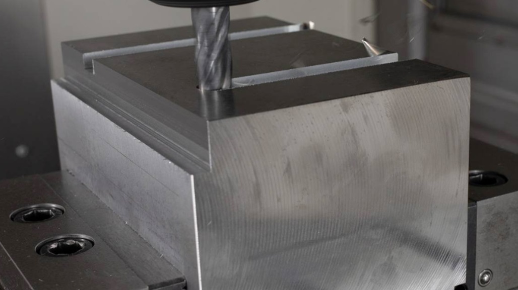
How to achieve good surface finish for turning components
General rules for surface finish:
The surface finish can often be improved by using a higher cutting speed
The insert geometry (neutral, positive and negative rake angles, as well as positive clearance angles) influences the surface finish
The selection of insert grade has some influence on surface finish
In the event of vibration tendencies, select a smaller nose radius
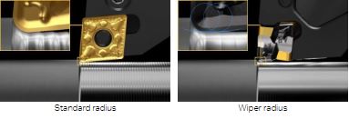
Wiper insert
Wiper inserts are capable of turning components at high feed rates—without losing the capability for generating good surface finishes or chip-breaking ability.
A general guideline is: Two times the feed rate, same surface finish. Same feed rate, twice as good surface finish.
Wiper inserts are designed to smooth the surface generated as the insert is fed along the workpiece; the wiper effect is primarily designed for straight-line turning and facing.
Learn how to choose the correct wiper geometry and read this article in its entirety here.
Previously Featured on Sandvik's Knowledge Center.